


APP - 13
A
PPENDICES
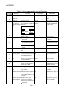
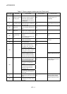
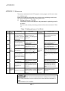
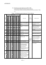
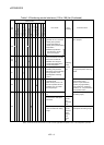
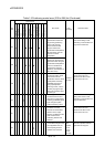
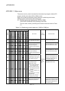
Table 1.5 Positioning control error (200 to 299) list (Continued)
Control mode
Error
code
Positioning
Fixed-pitch feed
Speed
Speed/position switching
Speed switching
Constant-speed
JOG
Manual pulse generator
Home position return
Position follow-up control
OSC
Speed control with
fixed position stop
Error cause
Error
processing
Corrective action
207
• The feed current value
exceeded the stroke limit
range during positioning
control. Only the axis
exceed the stroke limit
range is stored at the
circular/helical interpolation.
All interpolation axes are
stored in the linear
interpolation.
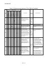
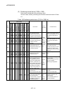
208
• The feed current value of
another axis exceeded the
stroke limit value during the
circular/helical interpolation
control or simultaneous
manual pulse generator
operation. (For detection of
other axis errors).
• Correct the stroke limit range or
travel value setting so that
positioning control is within the
range of the stroke limit.
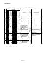
209
• An overrun occurred
because the setting travel
value is less than the
deceleration distance at the
speed/position switching
(CHANGE) signal input
during speed/position
switching control, or at the
proximity dog signal input
during home position return
of count type.
• Set the speed setting so that
overrun does not occur.
• Set the travel value so that
overrun does not occur.
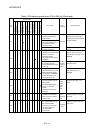
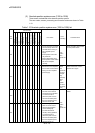
210
• The setting travel value
exceeded the stroke limit
range at the speed/position
switching (CHANGE) signal
input during the speed/
position switching control.
• Correct the stroke limit range or
setting travel value so that
positioning control is within the
range of stroke limit.
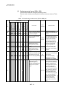
211
• During positioning control,
an overrun occurred
because the deceleration
distance for the output
speed is not attained at the
point where the final
positioning address was
detected.
Decelera-
tion stop
• Set the speed setting so that
overrun does not occur.
• Set the travel value so that
overrun does not occur.
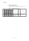
214
• The manual pulse generator
was enabled during the start
of the applicable axis, the
manual pulse generator
operation was executed.
Manual
pulse
generator
input is
ignored
until the
axis stops.
• Execute the manual pulse
generator operation after the
applicable axis stopped.