


A - 12
INTRODUCTION
Thank you for choosing the Q173HCPU/Q172HCPU Motion Controller.
Please read this manual carefully so that equipment is used to its optimum.
CONTENTS
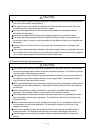
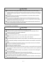
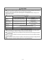
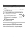
Safety Precautions .........................................................................................................................................A- 1
Revisions ........................................................................................................................................................A-11
Contents .........................................................................................................................................................A-12
About Manuals ...............................................................................................................................................A-16
1. OVERVIEW 1- 1 to 1- 6
1.1 Overview................................................................................................................................................... 1- 1
1.2 Features ................................................................................................................................................... 1- 3
1.2.1 Performance Specifications .............................................................................................................. 1- 3
1.2.2 Differences between Q173HCPU/Q172HCPU and Q173CPU(N)/Q172CPU(N).......................... 1- 5
2. POSITIONING CONTROL BY THE MOTION CPU 2- 1 to 2-14
2.1 Positioning Control by the Motion CPU................................................................................................... 2- 1
3. POSITIONING DEDICATED SIGNALS 3- 1 to 3-66
3.1 Internal Relays ......................................................................................................................................... 3- 2
3.1.1 Axis statuses ..................................................................................................................................... 3-12
3.1.2 Axis command signals ...................................................................................................................... 3-22
3.1.3 Common devices .............................................................................................................................. 3-29
3.2 Data Registers.......................................................................................................................................... 3-42
3.2.1 Axis monitor devices ......................................................................................................................... 3-46
3.2.2 Control change registers................................................................................................................... 3-52
3.2.3 Common devices .............................................................................................................................. 3-53
3.3 Motion Registers(#).................................................................................................................................. 3-57
3.4 Special Relays (SP.M) ............................................................................................................................. 3-58
3.5 Special Registers (SP.D) ......................................................................................................................... 3-60
4. PARAMETERS FOR POSITIONING CONTROL 4- 1 to 4-14
4.1 System Settings ....................................................................................................................................... 4- 1
4.2 Fixed Parameters..................................................................................................................................... 4- 2
4.2.1 Number of pulses/travel value per rotation....................................................................................... 4- 3
4.2.2 Backlash compensation amount....................................................................................................... 4- 5
4.2.3 Upper/lower stroke limit value........................................................................................................... 4- 5
4.2.4 Command in-position range.............................................................................................................. 4- 7
4.2.5 Speed control 10
multiplier setting for degree axis ........................................................................ 4- 8
4.3 Parameter Block....................................................................................................................................... 4-11
4.3.1 Relationships between the speed limit value, acceleration time, deceleration time and rapid stop
deceleration time............................................................................................................................... 4-13
4.3.2 S-curve ratio ...................................................................................................................................... 4-13