


3 - 19
3 POSITIONING DEDICATED SIGNALS
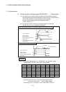
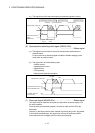
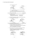
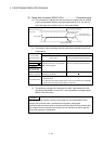
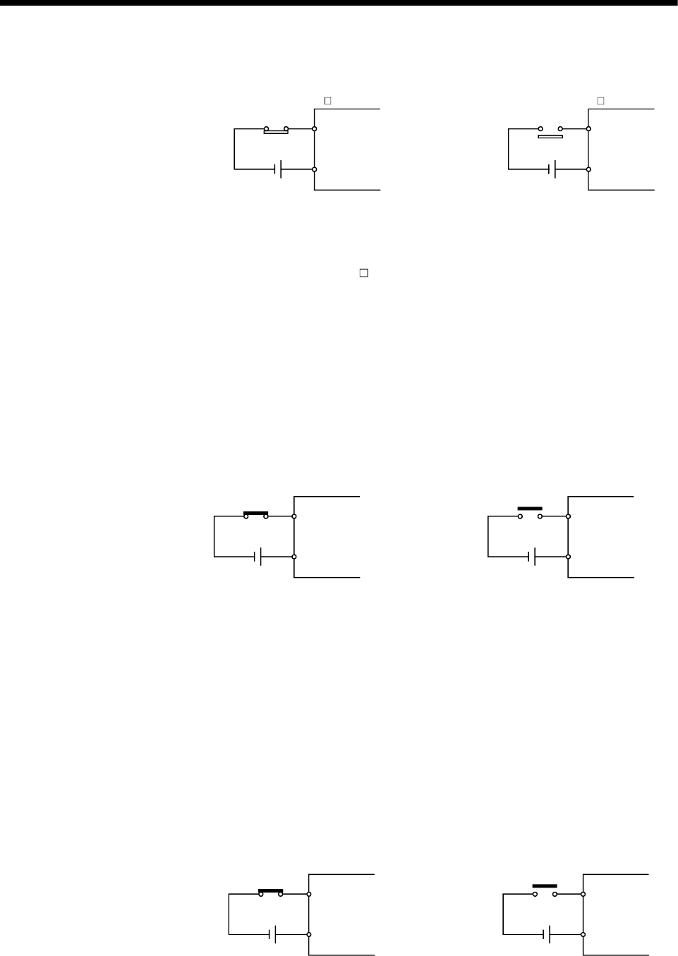
2) Servo amplifier input use
(Note-3)
RLS signal : ON
RLS
DI2
DICOM
RLS signal : OFF
RLS
DI2
DICOM
MR-J3- B
MR-J3- B
(Note-1): Refer to the "Q173HCPU/Q172HCPU Motion controller Programming Manual
(COMMON)" for an external signal.
(Note-2): Refer to the "Q173HCPU/Q172HCPU User’s Manual" for a pin configuration.
(Note-3): Refer to the "MR-J3-
B Servo Amplifier Instruction Manual" for a pin configuration.
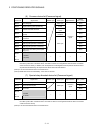
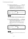
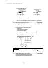
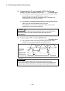
(14) STOP signal (M2413+20n) ........................................Status signal
(a) This signal is controlled by the ON/OFF state for the stop signal input
(STOP) of the Q172LX.
• Stop signal input of the Q172LX OFF ..... STOP signal: OFF
• Stop signal input of the Q172LX ON ....... STOP signal: ON
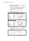
(b) The state of the stop signal input (STOP) of the Q172LX when the STOP
signal input is ON/OFF is shown below.
STOP signal : ON
Q172LX
STOP
STOP
COM
STOP signal : OFF
Q172LX
STOP
STOP
COM
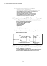
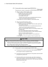
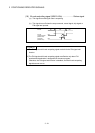
(15) DOG/CHANGE signal (M2414+20n)
(Note-1)
..................Status signal
(a) This signal turns on/off by the proximity dog input (DOG) of the
Q172LX/servo amplifier at the home position return.
This signal turns on/off by the speed/position switching input (CHANGE) of
the Q172LX at the speed/position switching control.
(There is no CHANGE signal in the servo amplifier.)
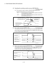
(b) When using the Q172LX, "Normally open contact input" and "Normally
closed contact input" of the system setting can be selected.
The state of the speed/position switching input (CHANGE) when the
CHANGE signal is ON/OFF is shown below.
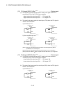
1) Q172LX use
(Note-2)
DOG/CHANGE signal : ON
Q172LX
DOG/CHANGE
DOG/CHANGE
COM
DOG/CHANGE signal : OFF
Q172LX
DOG/CHANGE
DOG/CHANGE
COM