


6 - 5
6 POSITIONING CONTROL
POINTS
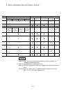
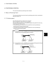
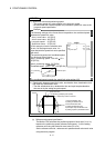
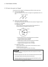
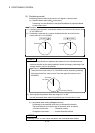
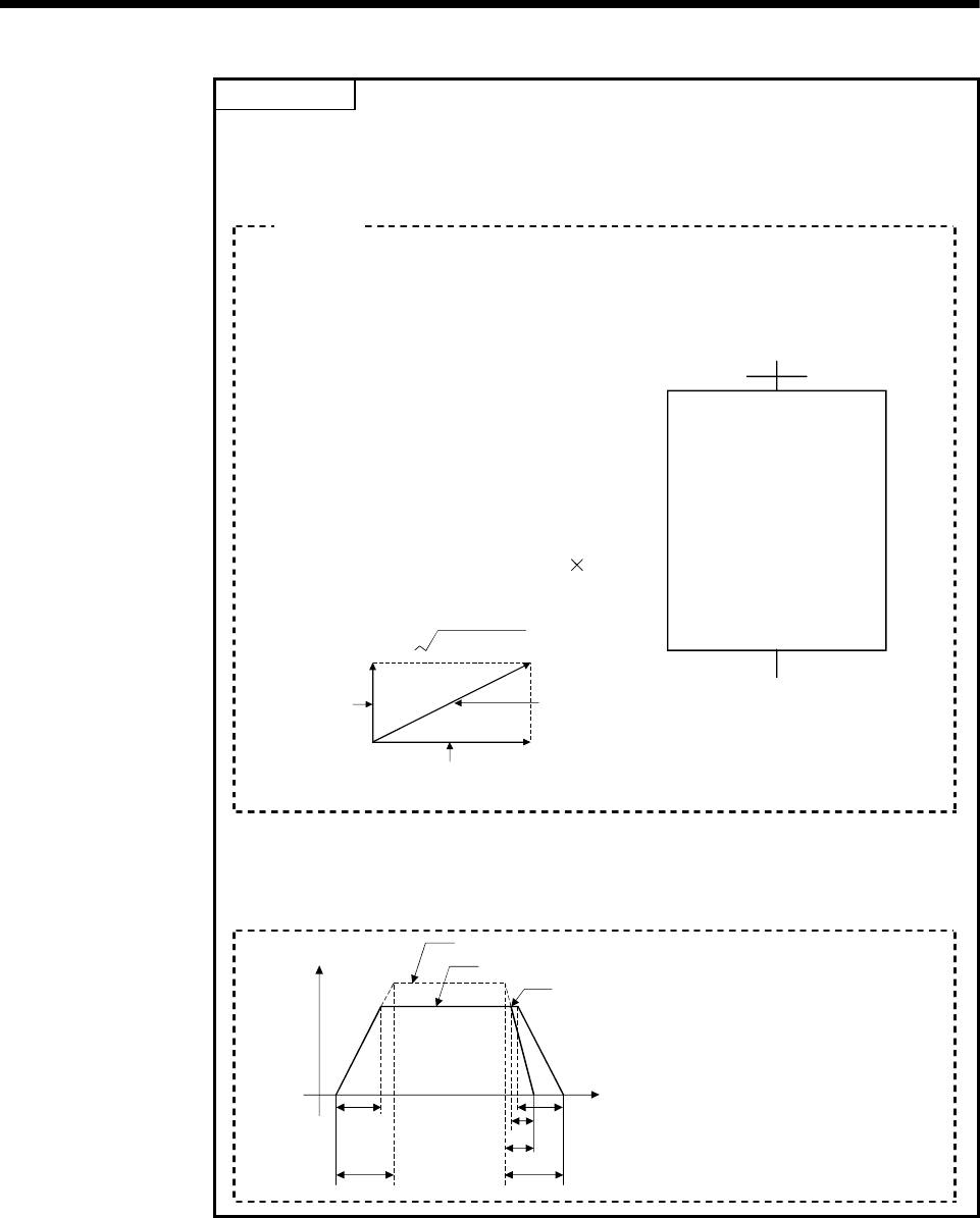
(1) Speed limit value and positioning speed
• The setting speed limit value applies to the long-axis speed.
• Be careful that the combined-speed may exceed the speed limit value at the
long-axis speed specification.
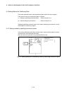
The following settings at the 2 axes linear interpolation, the combined-speed
exceeds the speed limit value.
Axis 1 travel value : 100 [PLS]
Axis 2 travel value : 200 [PLS]
Long-axis speed : 50 [PLS/s]
Speed limit value : 55 [PLS/s]
In this example, since the reference-axis
is axis 2 of the largest travel value, it is
controlled with the speed limit value specified
with axis 2.
The positioning speed and combined-speed
for each axis are as follows:
Axis 1 positioning speed : 100/ 200
50 =
25 [PLS/s]
Axis 2 positioning speed : 50 [PLS/s]
Combined-speed :
25 + 50 = 55.9[PLS/s]
22
Axis 1 positioning
speed
Axis 2 positioning speed
Combined-speed
<K 2>
INC-2
Axis
Axis
Long-axis speed
1,
2,
100
200
50
[PLS]
[PLS]
[PLS/s]
The combined-speed exceeds the speed limit value setting of 55.
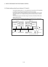
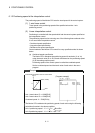
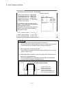
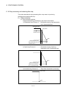
(2) Relationship between speed limit value, acceleration time, deceleration time
and rapid stop deceleration time.
• The real acceleration time, deceleration time and rapid stop deceleration
time are set by the setting long-axis speed.
Speed
Speed limit value
Positioning speed(long-axis speed)
Rapid stop cause occurrence
Time
1)
2) 4)
6)
5)
3)
1) Real acceleration time
2) Setting acceleration time
3) Real deceleration time
4) Setting deceleration time
5) Real rapid stop deceleration time
6) Setting rapid stop deceleration time
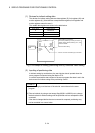
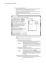
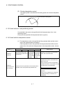
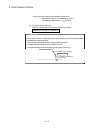
(c) Reference-axis speed specification
The Motion CPU calculates the positioning speed of other axes (V
1 to V3)
based on the positioning speed (reference-axis speed : V) of the setting
reference-axis using the each axis travel value (D
1 to D4).
Set the reference-axis No., reference-axis speed and each axis travel value
using the servo program.
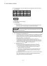
Exam
p
le