


APP - 47
A
PPENDICES
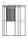
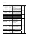
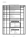
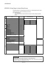
Table 2.2 Special register list (continued)
No. Name Meaning Details
Set by
(When set)
Remark
D9188
Motion operation
cycle
Motion operation
cycle
• The time when the motion operation cycle is stored in the [
µ
s] unit.
S(Operation cycle)
D9189
Error program
No.
Error program No. of
servo program
When the servo program setting error flag (M9079) turns on, the erroneous
servo program No. will be stored.
D9190
Error item
information
Error code of servo
program
When the servo program setting error flag (M9079) turns on, the error
code corresponding to the erroneous setting item will be stored.
S(Occur an error)
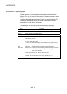
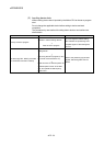
D9191
D9192
Servo amplifier
loading
information
Servo amplifier
loading information
• The loading status (loading: 1/non-loading: 0) of the servo amplifier checked
in initial process, and stored as the bit data.
D9191: b0 to b15 (axis 1 to axis 16)
D9192: b0 to b15 (axis 17 to axis 32)
• The axis which turned from non-loading to loading status after power-on is
handled as loaded. (However, the axis which turned from loading to non-
loading status remains as loaded.)
S(Initial processing)
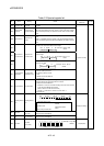
D9193
D9194
D9195
Real/virtual mode
switching error
information
Real/virtual mode
Switching
error code
• When a mode switching error occurs in real-to-virtual or virtual-to-real
mode switching, or a mode continuation error occurs in the virtual mode,
its error information is stored.
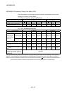
D9196
PC link
communication
error codes
PC link
communication error
codes
• The following error code is stored.
00: No error
01: Receiving timing error
02: CRC error
03: Communication response code error
04: Received frame error
05: Communication task start error
(Each error code is reset to "00" when normal communication is
restarted.)
S(Occur an error)
D9197
Operation cycle
of the Motion
CPU setting
Operation cycle
of the Motion CPU
setting
• The time when the setting operation cycle is stored in the [
µ
s] unit.
S(Initial processing)
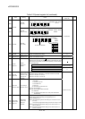
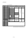
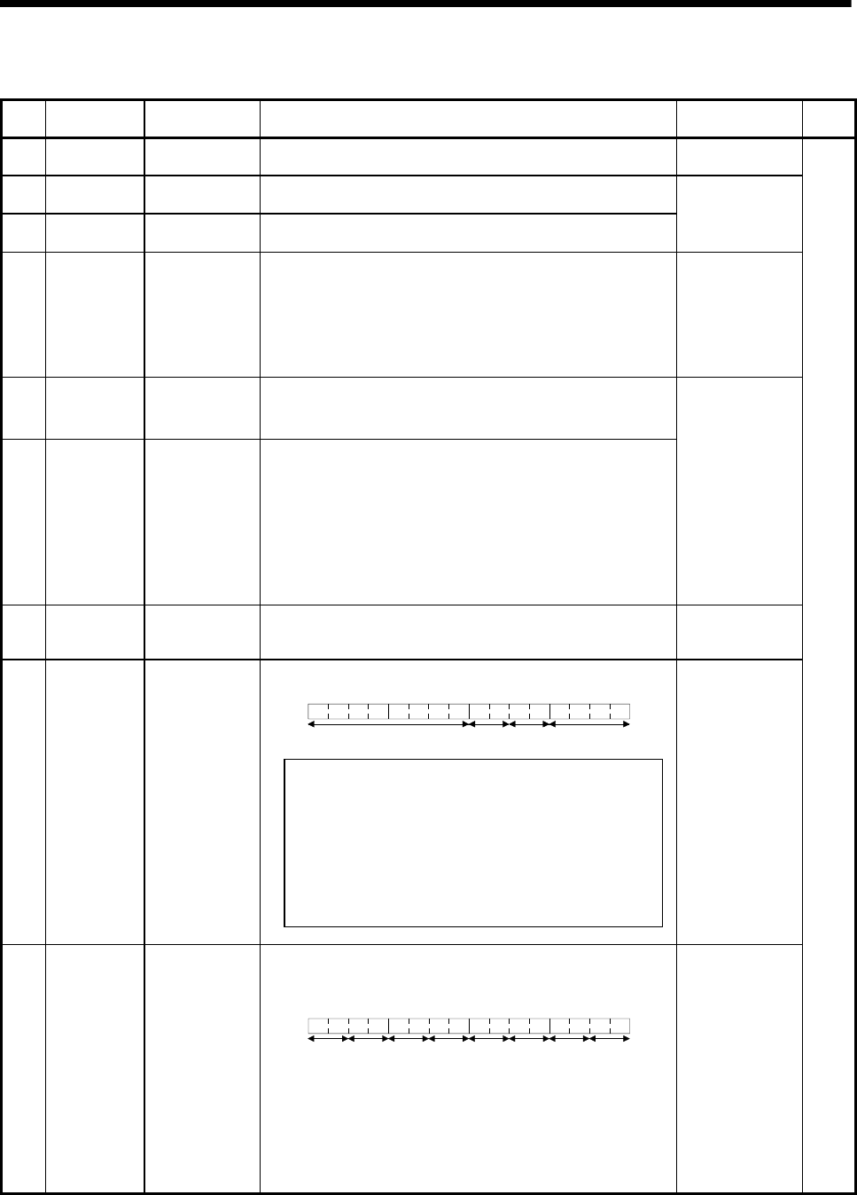
• The CPU switch status is stored in the following format.
B15 B12B11
B8
B7 B4 B3 B0
1)2)
No used.
3)
1) CPU switch status 0: RUN
1: STOP
2: L.CLR
2) Memory card switch Always OFF
3) Dip switch
B8 through B12 correspond to SW1
through SW5 of system setting switch 1.
0: OFF/1: ON
B13 through B15 is not used.
D9200 State of switch State of CPU switch
S(Main processing)
• Information concerning which of the following states the LEDs on the CPU
are in is stored in the following bit patterns.
• 0 is off, 1 is on, and 2 is flicker
B15 B12B11 B8 B7 B4 B3 B0
1
)
2
)
4
)
3
)
5
)
6
)
8
)
7
)
1): RUN 5): BOOT
2): ERROR 6): No used
3): M.RUN 7): No used
4): BAT.ALARM 8): MODE
D9201 State of LED State of CPU-LED
Bit patterns for MODE
0: OFF 1: Green
2: Orange
S(Change status)