


6 - 74
6 POSITIONING CONTROL
INH
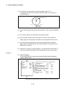
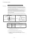
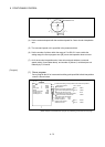
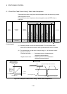
Incremental auxiliary point-specified helical interpolation control
[Control details]
The linear interpolation to other linear axis is executed performing circular interpolation
from current stop position (start point) to specified circular relative end address (X1,
Y1) or linear axis end point relative address (Z1), and the incremental helical
interpolation control is executed so that it may become a spiral course.
It goes around on the specified circle for the specified number of pitches, the circular
interpolation which had remainder specified is executed, and positioning to end
address is executed. The auxiliary point-specified circle specifies circular interpolation
method connected start point and end point at the seeing on the plane for which
performs circular interpolation.
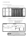
Operation details for incremental auxiliary point-specified helical interpolation are
shown below.
Number of pitches a
End point relative address (X
1,
Y
1,
Z
1
)
Start point
Helical interpolation
path
Circular interpolation
plane
Linear interpolation
travel value = Z
1
: Indicates setting range (Note)
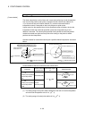
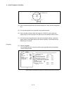
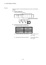
Positioning speed V
1
Start point
Radius R
Arc auxiliary point
address (X
2
, Y
2
)
Circular interpolation plane
End point relative address (X
1
, Y
1
)
: Indicates setting range
(Note)
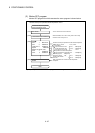
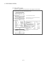
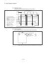
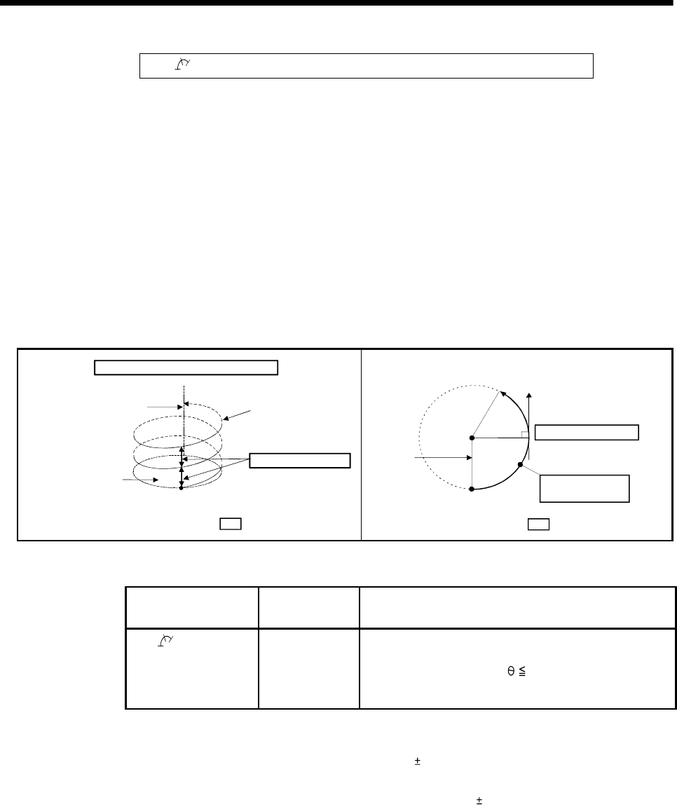
Control details for the servo instructions are shown below.
Instruction
Rotation direction
of servomotor
Controllable angle of arc
INH
Auxiliary point-
specified helical
interpolation
Clockwise (CW)/
Counter
clockwise (CCW)
0° <
360°
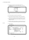
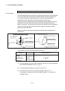
(1) The setting range of end point relative address for the both of circular interpolation
axis and linear interpolation axis is 0 to
(2
31
-1).
(2) The setting range of auxiliary point relative is 0 to
(2
31
-1).
(3) The maximum arc radius on the circular interpolation plane is (2
31
-1).
For example, the maximum arc radius for electronic gear 1:1 of unit [mm] is
214748364.7[
µm].