


6 -
163
6 POSITIONING CONTROL
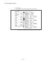
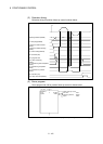
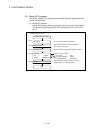
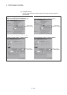
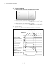
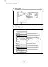
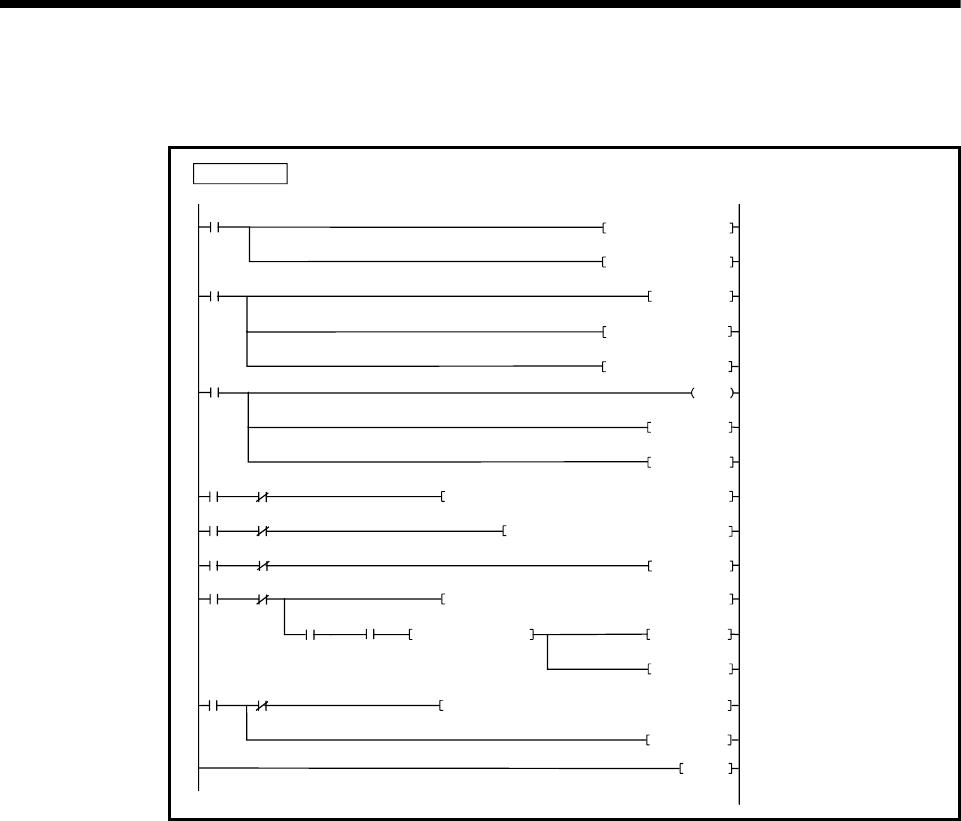
(b) PLC program
PLC program example for position follow-up control is shown below.
Substitutes 2 for D51 after program
start.
0
5
SM400
X0
M20RST
SP.DDWR H3E1 D4000 M0D1000D50
K2 D61MOVP
PLC program
18
30
4
2
M10
M0
M2
M20RST
66
M30
END
81
K2 D51
MOVP
M10PLS
M3240
M30RST
X1
M1
M0
M3
SP.SFCS H3E1 M2 D1100K150
M20SET
SP.DDRD H3E1
D1200 M4
D40D60
4
5
M20
M4
M2441 M2442
D1200 D1000
D=
M30SET
SP.DDWR H3E1
D4000 M6
D1300D50
M30RST
M6
14
K0 D1300
DMOV
K150000 D1000DMOV
Substitutes 2 for D61 after program
start.
Starts by turning X0 on.
Substitutes 150000 for D1000 .
Substitutes 0 for D1300 .
Reads data of D1000 for Multiple CPU
system No.2 by turning M10 on, and
writes to D4000 of CPU No.2.
Starts the Motion SFC program No.150.
After the Motion SFC program No.150
is started, reads data of D40 for Multiple
CPU system No.2 and stores in D1200
self CPU.
Resets M20 and sets M30 at the axis 3
positioning completion and D1200 =
D1000.
Reads data of D1300 for Multiple CPU
system No.2 by turning M30 on, and
writes to D4000 of CPU No.2.
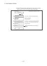
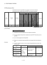
(Note): The CPU shared memory setting example for position follow-up control is shown next page.