


3 - 2
3 POSITIONING DEDICATED SIGNALS
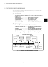
The positioning dedicated devices are shown below.
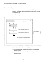
It indicates the device refresh cycle of the Motion CPU for status signal with the
positioning control, and the device fetch cycle of the Motion CPU for command signal
with the positioning control.
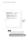
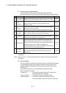
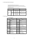
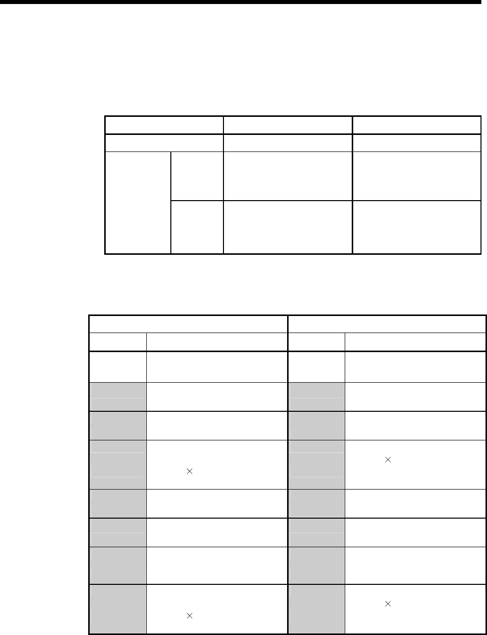
The operation cycle of the Motion CPU is shown below.
Item Q173HCPU Q172HCPU
Number of control axes Up to 32 axes Up to 8 axes
SV13
0.44ms/ 1 to 3 axes
0.88ms/ 4 to 10 axes
1.77ms/11 to 20 axes
3.55ms/21 to 32 axes
0.44ms/ 1 to 3 axes
0.88ms/ 4 to 8 axes
Operation cycle
(Default)
SV22
0.88ms/ 1 to 5 axes
1.77ms/ 6 to 14 axes
3.55ms/15 to 28 axes
7.11ms/29 to 32 axes
0.88ms/ 1 to 5 axes
1.77ms/ 6 to 8 axes
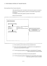
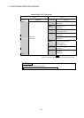
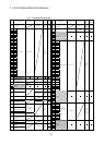
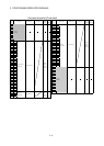
3.1 Internal Relays
(1) Internal relay list
SV13 SV22
Device No. Purpose Device No. Purpose
M0 M0
to
User device
(2000 points)
to
User device
(2000 points)
M2000 M2000
to
Common device
(320 points)
to
Common device
(320 points)
M2320 M2320
to
Special relay allocated device (Status)
(80 points)
to
Special relay allocated device (Status)
(80 points)
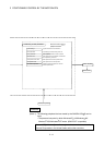
M2400 M2400
to
Axis status
(20 points
32 axes)
to
Axis status
(20 points
32 axes)
Real mode……Each axis
Virtual mode….Output module
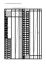
M3040 M3040
to
Unusable
(32 points)
to
Unusable
(32 points)
M3072 M3072
to
Common device (Command signal)
(64 points)
to
Common device (Command signal)
(64 points)
M3136 M3136
to
Special relay allocated device
(Command signal)
(64 points)
to
Special relay allocated device
(Command signal)
(64 points)
M3200 M3200
to
Axis command signal
(20 points
32 axes)
to
Axis command signal
(20 points
32 axes)
Real mode……Each axis
Virtual mode….Output module