


3 - 51
3 POSITIONING DEDICATED SIGNALS
[Internal processing]
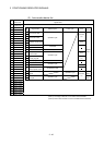
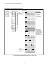
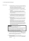
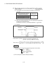
(a) The positioning data ((1) to (14)) of points 0 to 6 is input to the Motion CPU
by the starting. The last point "6" of the input data to be input is stored in the
data set pointer for constant-speed control at this time.
The "6" stored in the data set pointer for constant-speed control indicates
that updating of the positioning data stored in points 0 to 6 is possible.
(b) The positioning data ((A) to (D)) of points 0 to 1 is updated using the Motion
SFC program.
The last point "1" of the positioning data to be rewritten is stored in the
updated data set pointer (which must be controlled by the user in the
Motion SFC program). Updating of positioning data of points 2 to 6 (data (5)
to (14)) remains possible.
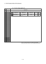
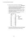
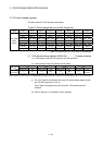
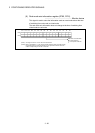
(c) On completion of the positioning for point 0, the value in the data set pointer
for constant-speed control is automatically incremented by one to "7".
The positioning data ((1) to (2)) of point 0 is discarded and the positioning
data ((15) to (16)) for point 7 is input to the Motion CPU at this time.
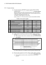
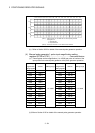
(d) Hereafter, whenever positioning of each point is completed, the positioning
data shifts one place.
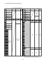
The positioning data that can be updated is the data after that indicated by
the updated data set pointer: this is the data which has not yet been input
to the Motion CPU.
Even if the values of the indirect devices D8 and D10 are updated by the
Motion SFC program after the positioning completion of the point 3, the
positioning data of point 2 that is input to the Motion CPU will not be
updated and the second positioning will be executed using the unupdated
data. The data set pointer for constant-speed control has not yet been input
to the Motion CPU, and indicates the positioning data which a user can
update using the Motion SFC program.
POINT
Number of points that can be defined by a repeat instruction
• Create the servo program at least eight points.
• If there are less than eight points and they include pass points of few travel value,
the positioning at each point may be completed, and the data input to the Motion
CPU, before the data has been updated using the Motion SFC program.
• Create a sufficient number of points to ensure that data will not be input before the
Motion CPU has updated the values in the indirect devices.
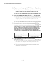
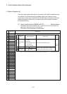
(13) Travel value change register (D16+20n, D17+20n)
....…….. Command device
This area is used when the travel value of the position control is changed at the
speed/position switching control (Refer to Section 6.15).
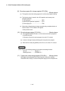
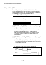
(14) Real current value at STOP input storage register
(D18+20n, D19+20n) .............……………………... Monitor device
This register stores the real current value at the STOP signal (STOP) input of
the Q172LX.