


6 - 62
6 POSITIONING CONTROL
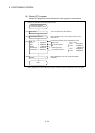
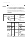
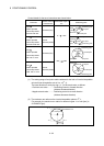
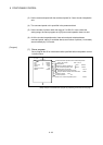
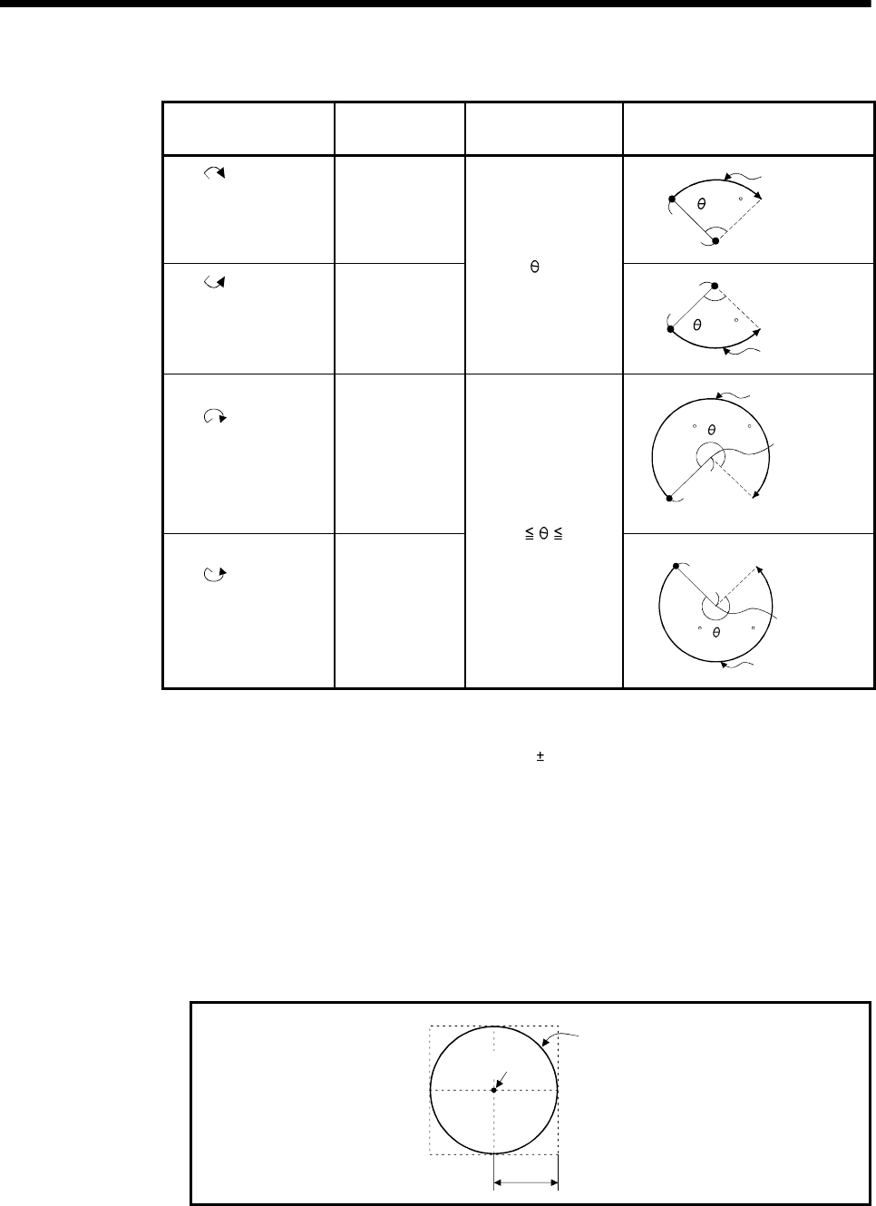
Control details for the servo instructions are shown below.
Instruction
Rotation direction
of servomotor
Controllable angle of
arc
Positioning pass
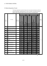
INH
Radius-specified
helical interpolation
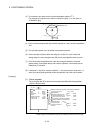
less than CW 180°
Clockwise (CW)
Positioning path
End point
Radius R
Central point
<180
Start
point
INH
Radius-specified
helical interpolation
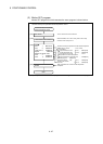
less than CCW 180°
Counter
clockwise (CCW)
0° <
< 180°
Central point
Radius R
Start
point
End point
Positioning path
<180
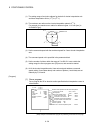
INH
Radius-specified
helical interpolation
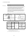
CW 180° or more
Clockwise (CW)
Positioning path
180 360
Central point
End point
Start point
Radius R
<
=
<
=
INH
Radius-specified
helical interpolation
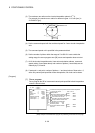
CCW 180° or more
Counter
clockwise (CCW)
180°
360°
Radius R
Start point
End point
Positioning path
Central point
180 360
<
=
<
=
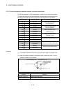
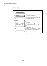
(1) The setting range of end point relative address for the both of circular interpolation
axis and linear interpolation axis is 0 to
(2
31
-1).
The travel direction is set by the sign (+/ -) of the travel value, as follows:
• Positive travel value .............Positioning control to forward direction
(Address increase direction)
• Negative travel value............Positioning control to reverse direction
(Address decrease direction)
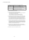
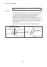
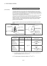
(2) The maximum arc radius on the circular interpolation plane is 2
31
-1.
For example, the maximum arc radius for electronic gear 1:1 of unit [mm] is
214748364.7[
µm].
Maximum arc
2
31
-1-2
31
2
31
-1
0
Radius R
Arc central point