


6-35
Performance Tests – Option 011
11. Receiver Input Impedance
11. Receiver Input Impedance
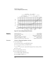
Perform this test to verify the return loss of each of the analyzer’s receiver
inputs.
Required
Equipment
Test set, 50
Ω
. . . . . . . . . . . . . . . . . . . . . . . . . .Agilent 85044A/85046A/85047A
2-way Power Splitter, 50
Ω
. . . . . . . . . . . . . . . . . . .Agilent 11667A Option 001
Attenuator, 10 dB . . . . . . . . . . . . . . . . . . . . . . . . . . .Agilent 8491A Option 010
Termination, 50
Ω
. . . . . . . . . . . . . . . . . . . . . . . . . . . . . . . . . . . . . Agilent 908A
Calibration kit, 50
Ω
, Type-N. . . . . . . . . . . . . . . . . . . . . . . . . . . Agilent 85032B
Adapter, APC-7 to Type-N (m) . . . . . . . . . . . . . . . . . . . . . . . . Agilent 11525A
RF cable set, 50
Ω
, Type-N . . . . . . . . . . . . . . . . . . . . . . . . . . . . Agilent 11851B
RF cable, 50
Ω
, 7 mm . . . . . . . . . . . . . . . . . . . . . . . . . . . Part of Agilent 11857D
Procedure
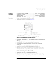
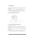
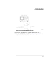
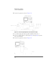
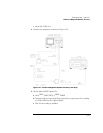
1
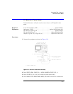
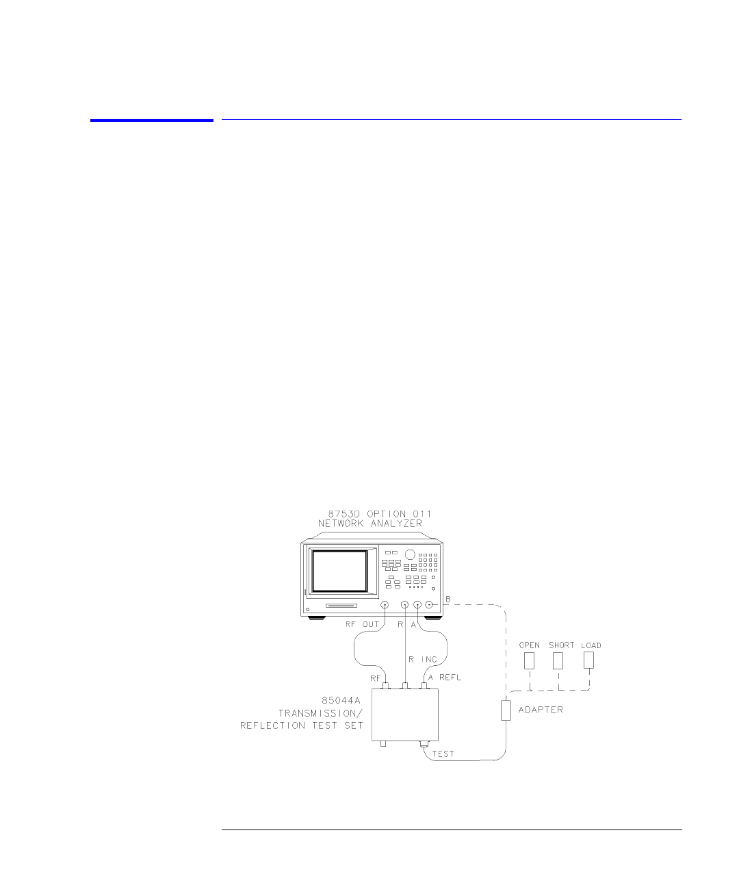
Connect the equipment as shown in Figure 6-17.
• If you are using the Agilent 85044A test set, set the attenuation to 0 dB.
• If you are using the Agilent 85046A or 85047A test set, connect the test set
interface cable to the analyzer and use the test set port 1.
Figure 6-17. Receiver B Input Impedance Test Setup