


6-9
Performance Tests – Option 011
3. Receiver Minimum R Channel Level
31
Press
MENU
,
CW FREQ
,
300
,
k/m
. Set the power calibration factor for this CW
frequency.
32
On the “Performance Test Record”, copy the “Path Loss” value, previously
calculated for this CW frequency, into the “Pass Loss” column.
33
Calculate the calibrated source power level using this formula:
Calibrated Power Level = 10 – Loss
34
Write the result in the “Calibrated Power Level” column.
35
Write the power meter reading under the “Measured Value” column on the
“Performance Test Record”.
36
Calculate the power level accuracy using this formula:
Calibrated Power Level – Measured Value = Power Level Accuracy
37
Write this value on the “Performance Test Record”.
38
Repeat Step 31 through Step 37 for the other CW frequencies listed on the
“Performance Test Record”.
In Case of
Difficulty
1
Ensure that the power meter and power sensor are operating to specification.
2
Inspect the power splitter connectors. Poor match at these connections can
generate power reflections that can cause the analyzer to appear to be out of
specification.
3
Inspect the analyzer
RF OUT
connector for damage.
4
If any test fails, perform the “RF Output Power Correction Constants (Test
47)”, located in the “Adjustments and Correction Constants” chapter of the
Agilent 8753D Option 011 Service Guide
.
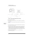
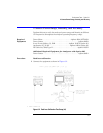
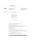
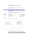
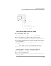
3. Receiver Minimum R Channel Level
Perform this test to verify the minimum R channel input power level at which
phase lock can be accomplished.