6-21
Performance Tests – Option 011
7. Receiver Magnitude Frequency Response
7. Receiver Magnitude Frequency Response
Perform this test to verify how well the analyzer transfers information from
the RF to IF, and how accurately it processes and displays that information.
Required
Equipment
Power Meter . . . . . . . . . . . . . . . . . . . . . . . . . . . . . . . .Agilent 436A/437B/438A
Power Sensor . . . . . . . . . . . . . . . . . . . . . . . . . . . . . . . . . . . . . . . Agilent 8482A
2-way Power Splitter, 50
Ω
. . . . . . . . . . . . . . . . . . .Agilent 11667A Option 001
Attenuator, 10 dB . . . . . . . . . . . . . . . . . . . . . . . . . . .Agilent 8491A Option 010
RF cable set, 50
Ω
, Type-N . . . . . . . . . . . . . . . . . . . . . . . . . . . . Agilent 11851B
Adapter, Type-N (m) to Type-N (m) . . . . . . . . . . . . . . Agilent P/N 1250-1475
Adapter, Type-N (f) to Type-N (f) . . . . . . . . . . . . . . . Agilent P/N 1250-1472
Additional Equipment Required for Analyzers with Option 006
Power Sensor . . . . . . . . . . . . . . . . . . . . . . . . . . . . . . . . . . . . . . . Agilent 8481A
Procedure Input R Magnitude Frequency Response
1
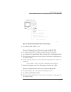
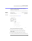
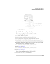
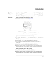
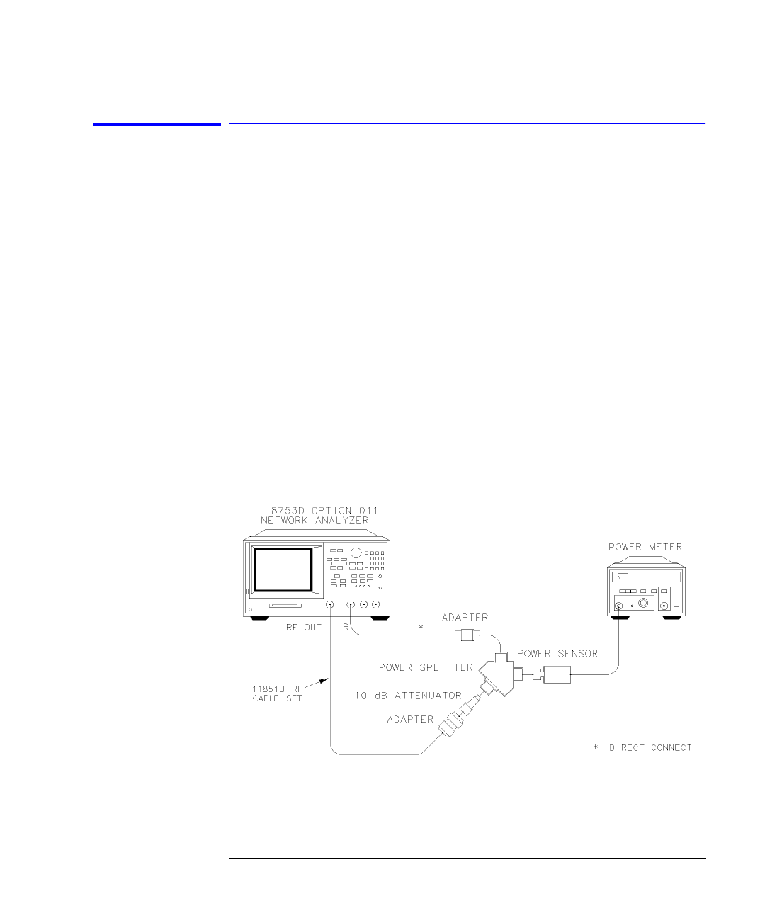
Connect the equipment as shown in Figure 6-9.
Figure 6-9. Magnitude Frequency Response Test Setup (Receiver Input R)
2
Zero and calibrate the power meter. Set it to measure dBm.


