


6-11
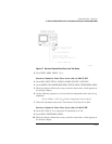
Performance Tests – Option 011
3. Receiver Minimum R Channel Level
c
If the analyzer still doesn’t phase lock, continue increasing the source output
power until phase lock is achieved.
d
Write the marker value in the “Performance Test Record”.
• Repeat Step 4 through Step 6 for the other CW frequencies listed in the “Per-
formance Test Record”.
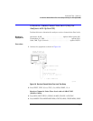
In Case of
Difficulty
WARNING
These servicing instructions are for use by qualified personnel only.
To avoid electrical shock, do not perform any servicing unless you are
qualified to do so.
WARNING
The opening of covers or removal of parts is likely to expose
dangerous voltages. Disconnect the instrument from all voltage
sources while it is being opened.
WARNING
The power cord is connected to internal capacitors that may remain
live for five seconds after disconnecting the plug from its power
supply.
1
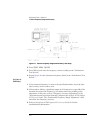
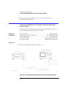
Check the flexible RF cable between the R sampler assembly and the A11
phase lock assembly. Make sure it is connected between A11J1 (PL IF IN) and
1st IF Out.
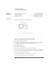
2
Using an ohmmeter, verify that the RF cable is
not
open. In addition, examine
both the cable connectors - measure the resistance between the cable center
pin and the cable connector. The ohmmeter should display a high resistance
reading.
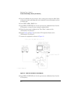
3
Check the R sampler by substituting it with the A sampler and rerun the test.
a
Move cable W8 to the A sampler.
b
Use a 10 dB attenuator between the RF OUT and input A.
c
Repeat the test.
d
Select the A sampler by pressing
MEAS
,
INPUT PORTS
,
A
in Step 2.
e
If the test fails, replace the A11 assembly.
4
Verify that the high/low band adjustments are still within specifications. For
more information on how to perform this task, refer to the “High/Low Band
Transition Adjustment”, located in the “Adjustments and Correction
Constants” chapter in the
Agilent 8753D Option 011 Service Guide
.