


6-14
Performance Tests – Option 011
5. Receiver Channel Noise Floor Level (Only for Analyzers without Option 006)
In Case of
Difficulty
WARNING
These servicing instructions are for use by qualified personnel only.
To avoid electrical shock, do not perform any servicing unless you are
qualified to do so.
WARNING
The opening of covers or removal of parts is likely to expose
dangerous voltages. Disconnect the instrument from all voltage
sources while it is being opened.
WARNING
The power cord is connected to internal capacitors that may remain
live for five seconds after disconnecting the plug from its power
supply.
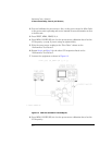
1
Check the R sampler assembly by substituting it with the A sampler assembly.
2
Move the flexible RF cable (currently connected to the R sampler assembly) to
the A sampler assembly.
3
Use a 10 dB attenuator between the RF OUT and the analyzer receiver input A.
4
Repeat the test. In Step 4, press
MEAS
,
INPUT PORTS
,
A
.
5
If the test still fails, suspect the A11 phase lock board assembly.
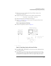
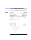
5. Receiver Channel Noise Floor Level (Only for
Analyzers without Option 006)
Perform this test to determine the analyzer receiver channel noise floor levels.
Required
Equipment
Attenuator, 20 dB . . . . . . . . . . . . . . . . . . . . . . . . . . . Agilent 8491A Option 020
Termination (2), 50
Ω
. . . . . . . . . . . . . . . . . . . . . . . . . . . . . . . . . . .Agilent 908A
Cable, 50
Ω
, Type-N, 24 inch . . . . . . . . . . . . . . . . . . . . . . . . . . .Agilent 11851B
Procedure
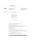
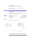
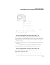
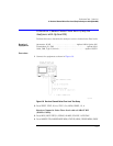
1
Connect the equipment as shown in Figure 6-7.