


7. Servo Parameters
7.1 MDS-B-SVJ2
82
7.1 MDS-B-SVJ2
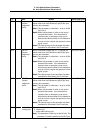
(1) Details for servo parameters
For parameters marked with a (PR) in the table, turn the NC power OFF after setting. After the power is
turned ON again, the parameter is validated.
!
CAUTION
!
In the explanation on bits, set all bits not used, including blank bits, to “0”.
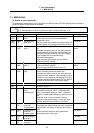
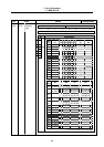
No. Items Details Setting range
2201
(PR)
SV001
PC1
Motor side gear
ratio
1 to 32767
2202
(PR)
SV002
PC2
Machine side
gear ratio
Set the motor side and machine side gear ratio.
For the rotary axis, set the total deceleration
(acceleration) ratio.
Even if the gear ratio is within the setting range, the
electronic gears may overflow and cause an alarm.
1 to 32767
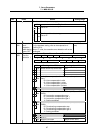
2203 SV003
PGN1
Position loop
gain 1
Set the position loop gain. The standard setting is
“33”.
The higher the setting value is, the more precisely
the command can be followed and the shorter the
positioning time gets, however, note that a bigger
shock is applied to the machine during
acceleration/deceleration.
When using the SHG control, also set SV004
(PGN2) and SV057 (SHGC).
1 to 200
(rad/s)
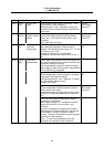
2204 SV004
PGN2
Position loop
gain 2
When using the SHG control, also set SV003
(PGN1) and SV057 (SHGC).
When not using the SHG control, set to “0”.
0 to 999
(rad/s)
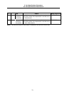
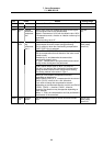
2205 SV005
VGN1
Speed loop
gain
Set the speed loop gain.
Set this according to the load inertia size.
The higher the setting value is, the more accurate
the control will be, however, vibration tends to occur.
If vibration occurs, adjust by lowering by 20 to 30%.
The value should be determined to be 70 to 80% of
the value at the time when the vibration stops.
1 to 999
2206 Not used. Set to “0”. 0
2207 Not used. Set to “0”. 0
2208 SV008
VIA
Speed loop
lead
compensation
Set the gain of the speed loop integration control.
The standard setting is “1364”. During the SHG
control, the standard setting is “1900”. Adjust the
value by increasing/decreasing it by about 100 at a
time.
Raise this value to improve contour tracking
precision in high-speed cutting. Lower this value
when the position droop vibrates (10 to 20Hz).
1 to 9999
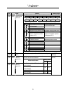
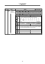
2209 SV009
IQA
Current loop q
axis lead
compensation
1 to 20480
2210 SV010
IDA
Current loop d
axis lead
compensation
1 to 20480
2211 SV011
IQG
Current loop q
axis gain
1 to 2560
2212 SV012
IDG
Current loop d
axis gain
Set the gain of current loop.
As this setting is determined by the motor’s electrical
characteristics, the setting is fixed for each type of
motor.
Set the standard values for all the parameters
depending on each motor type.
1 to 2560