


8. Spindle Parameters
8.5 Supplement
267
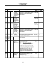
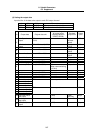
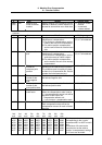
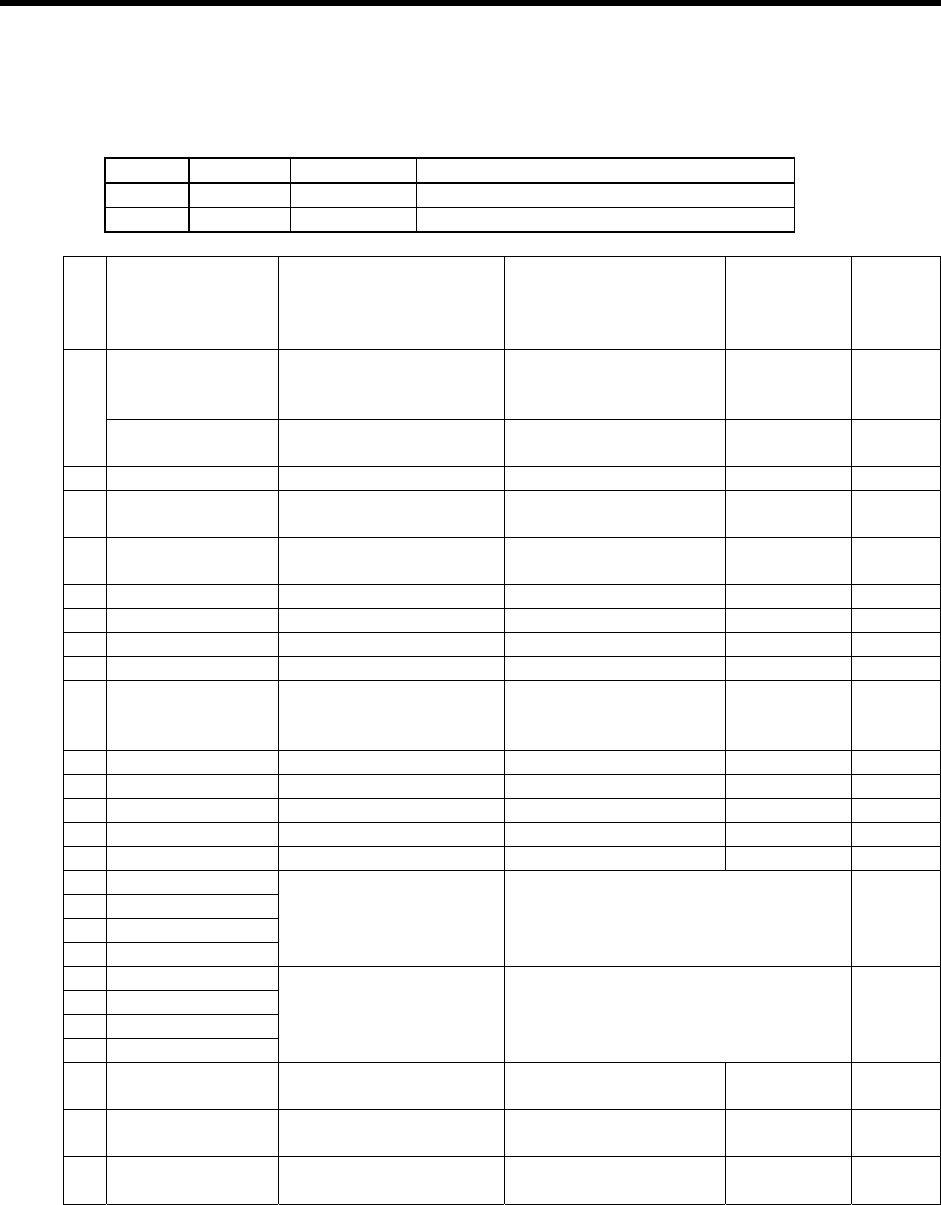
(2) Setting the output data
Input the No. of the data to be output to each D/A output channel.
# No. Abbrev Parameter name
3453 SP253 DA1NO D/A output channel 1 data No.
3454 SP254 DA2NO D/A output channel 2 data No.
No. Output data Original data unit
Standard setting value
for output scale
(Setting values in
SP255, SP256)
Standard
output unit
Output
cycle
ch1: Speed meter
output
10V=max. speed
(0=0V)
0 Depends on
the max.
speed
3.55ms
0
ch2: Load meter
output
10V=120% load (0=0V) 0 Rated
12%/V
3.55ms
1 –
2
Current command Rated 100% = 4096 8 Rated
20%/V
3.55ms
3
Current feedback Rated 100% = 4096 8 Rated
20%/V
3.55ms
4 Speed feedback r/min 13 500rpm/V 3.55ms
5 –
6 Position droop 1° = (64000/65536) 671 10°/V 888µs
7 –
8
Feedrate (F∆T) 1° = (64000/65536) 629
(When communicating
by 3.5ms)
500rpm/V 888µs
9 –
10 Position command 1° = (64000/65536) 19 (18.64) 360°/V 888µs
11 –
12 Position feedback 1° = (64000/65536) 19 (18.64) 360°/V 888µs
13 –
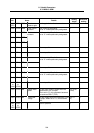
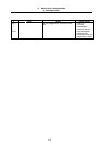
80 Control input 1
81 Control input 2
82 Control input 3
83 Control input 4
HEX Bit correspondence 3.55ms
84 Control output 1
85 Control output 2
86 Control output 3
87 Control output 4
HEX Bit correspondence 3.55ms
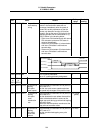
125
Saw-tooth wave
test output
0 (256) Cycle
227.5ms
444µs
126
Rectangular wave
test output
0 (256) Cycle 1.7ms 444µs
127
2.5V(data0) test
output
0 (256) – 444µs