


7. Servo Parameters
7.4 Supplement
173
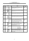
7.4.3 Lost Motion Compensation
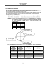
When the motor is to rotate in the clockwise direction (looking from the load side) at the command for
the + direction, the command direction is CW. Conversely, when the motor is to rotate in the
counterclockwise direction, the command direction is CCW.
This rotation direction can be set with the CNC machine parameters. Note that the meaning of the ± will
differ for some servo parameters according to this motor rotation direction. The servo parameters
affected by CW/CCW are shown below.
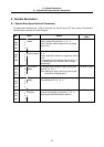
SV016 (LMC1), SV041 (LMC2) (When different values are set for SV016 and SV041)
SV031 (OVS1), SV042 (OVS2) (When different values are set for SV031 and SV042)
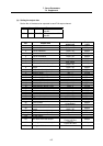
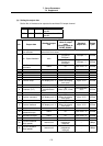
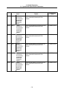
<Example> If the lost motion compensation amount is to be changed according to the direction,
the compensation amount at the quadrant changeover point of each arc where the
lost motion compensation is applied will be as shown below according to the
command polarity.
CW CCW
A X: SV041 X: SV016
B Y: SV016 Y: SV041
C X: SV016 X: SV041
D Y: SV041 Y: SV016
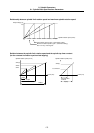
+X-X
-Y
+Y
The Y axis command
direction changes from
the – to + direction.
The X axis command
direction changes from
the – to + direction.
The X axis command
direction changes from
the + to – direction.
The Y axis command
direction changes from
the + to – direction.
A
B
C
D
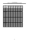
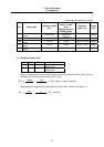
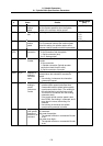
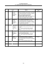
(Note) The setting value for the parameter is “0” or “-1”, the compensation amount is determined as
shown below.
Setting value
for SV016
(Setting value
for SV031)
Setting value
for SV041
(Setting value
for SV041)
Compensation
amount
in + direction
Compensation
amount
in - direction
0 0 No compensation No compensation
n 0 n n
0 m m m
n m n m
n -1 n No compensation
-1 m No compensation m