


9. Machine Error Compensation
9.2 Setting Compensation Data
273
9.2 Setting Compensation Data
Compensation data can be set according to either absolute or incremental system.
"#4000:Pinc" 0: Absolute system
1: Incremental system
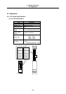
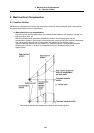
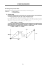
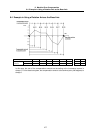
(1) Absolute system
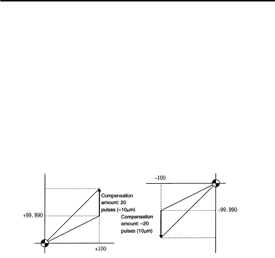
Feed from the reference point to each division point is executed as shown in the following figure.
The following is obtained at this time. Set it as the compensation amount.
(Specified position – Real machine position) × 2 (Unit of output)
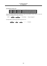
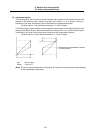
For example‚ assume that the feed from the reference point to the +100mm position is executed.
Also‚ assume that the real machine position is 99.990mm. In this case‚ the following value is
defined as the compensation amount used at the +100mm position:
(100000 – 99990) × 2 = 20 pulses
The resultant value is defined as the compensation amount. Assume that the real machine position
resulting when feed to the –100mm position is executed‚ is –99.990mm. In this case‚ the following
value is defined as the compensation amount used at the –100mm position:
(–100000 – (–99990)) × 2 = –20 pulses