


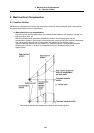
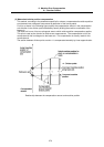

9. Machine Error Compensation
9.1 Function Outline
271
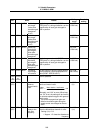
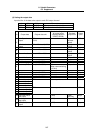
# Item Details Setting range
4000
(PR)
Pinc Machine error
offset increment
method
Specify whether the incremental volume
method or absolute volume method is to
be used to set machine error offset data.
0: Absolute volume
method
1: Incremental
volume method
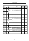
<1st axis>
# Item Details Setting range
4001 cmpax Basic axis Specify the basic axis address for
machine error compensation.
1) For pitch error compensation‚ set the
name of the axis to be compensated.
2) For relative position compensation‚
set the name of the axis to be the base
axis.
X, Y, Z, U, V, W, A,
B, or C axis address
4002 drcax Compensation
axis
Set the compensation axis address for
machine error compensation.
1) For pitch error compensation‚ set the
same axis name as "#4001 cmpax".
2) For relative position compensation‚
set the name of the axis to be actually
compensated.
X, Y, Z, U, V, W, A,
B, or C axis address
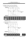
4003 rdvno Division point
number at
reference point
position
Set the compensation data No. corre-
sponding to the reference point position.
The reference point is actually the base‚
so there is no compensation No. Set the
number that is decremented by 1.
4101 to 5124
4004 mdvno Division point
number at the
most negative
side
Set the compensation data No. that is on
the farthest negative side.
4101 to 5124
4005 pdvno Division point
number at the
most positive side
Set the compensation data No. that is on
the farthest positive side.
4101 to 5124
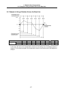
4006 sc Compensation
scale factor
Set the compensation amount’s scale.
When the compensation scale is set to
“1”, the compensation amount unit will be
the same as the output unit.
Compensation amount unit
= unit of output × compensation scale
0 to 99
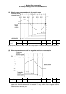
4007 spcdv Division interval Set the interval to divide the basic axis.
Each compensation data will be the
compensation amount for each of these
intervals.
1 to 9999999(µm)
2nd
axis
3rd
axis
4th
axis
5th
axis
6th
axis
7th
axis
8th
axis
9th
axis
10th
axis
4011
4012
4013
4014
4015
4016
4017
4021
4022
4023
4024
4025
4026
4027
4031
4032
4033
4034
4035
4036
4037
4041
4042
4043
4044
4045
4046
4047
4051
4052
4053
4054
4055
4056
4057
4061
4062
4063
4064
4065
4066
4067
4071
4072
4073
4074
4075
4076
4077
4081
4082
4083
4084
4085
4086
4087
4091
4092
4093
4094
4095
4096
4097
Set the parameters
corresponding to the 1st axis’
parameters 4001 to 4007 for each
axis.
A maximum of 6 axes can be
controlled‚ but as the relative
position is compensated‚ settings
for 10 axes can be made.