


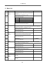


13. Indexing Axis Parameters
287
13. Indexing Axis Parameters
(Note) These parameters are used only with the G64T.
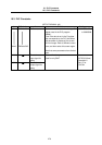
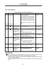
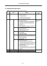
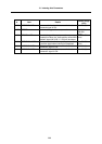
# Item Details
Setting range
(unit)
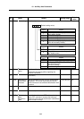
26251
METHOD Select the index command method.
0: Matrix command
1: Single command
2: BCD command (without parity)
3: BCD command (with parity)
0/1/2/3
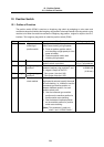
26252 AUX bit0 Select the rotary axis' control method.
0: Non-endless method
Positioning is carried out without extending
over 0.000°. Thus, the rotation direction is
automatically determined according to the
command.
1: Endless method
Positioning is carried out with the designated
rotation direction or a short cut.
0 to F
Set as a HEX
value.
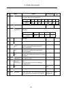
bit1 Validates addition/subtraction with the index
position command input.
0: Addition/subtraction invalid
1: Addition/subtraction valid
bit2 Select the valid width of external data input/output
function's IN data.
0: 16 bits (IN0 to IN15)
1: 24 bits (IN0 to IN23)
bit3 When the "request fixed" signal is ON, the parity
of the IN data equivalent to the valid width set in
#26252 bit2 is checked.
0: Does not check parity
1: Checks parity
bit4 Select the external positioning stop mode.
0: Retraction stop mode
After decelerating to a stop, the axis is
retracted to the position where the signal was
input (point where deceleration started). Then
the index position compensation amount is
calculated and set.
1: Deceleration stop mode
A
fter decelerating to a stop, the index position
compensation amount is calculated and set at
that point.
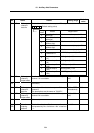
26253 JOG CLAMP SPEED 1 Set JOG speed 1 or indexing speed clamp 1.
26254 JOG CLAMP SPEED 2 Set JOG speed 2 or indexing speed clamp 2.
26255 JOG CLAMP SPEED 3 Set JOG speed 3 or indexing speed clamp 3.
1 to 1000000
(
mm/min, °/min)