


Hardware Installation
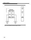
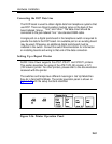
Connecting the DCP Data Line
The DCP board is used to obtain digital data from telephone systems that
use DCP. There are three 8-position modular jacks on the back of the
board labeled “phone,
“ “line,” and “other.” The data circuit should be
connected to the jack labeled “line.” Use standard D8W cable.
A single port on a digital ports board in the telephone switch is required to
provide the data to the DCP board. An available port on an existing board
may be used. Otherwise, an additional digital ports board must be
installed in the switch. Consult the switch documentation for information
on installing boards and wiring to that end of the data connection.
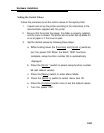
Setting Up a Report Printer
AUDIX Voice Power supports the AT&T 470/471 and 570/571 printers.
This section describes the setup of the AT&T 570 (80 column) or 571
(132 column) printer. For other printers, please refer to the documentation
received with the printer.
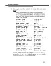
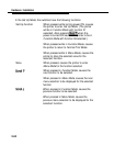
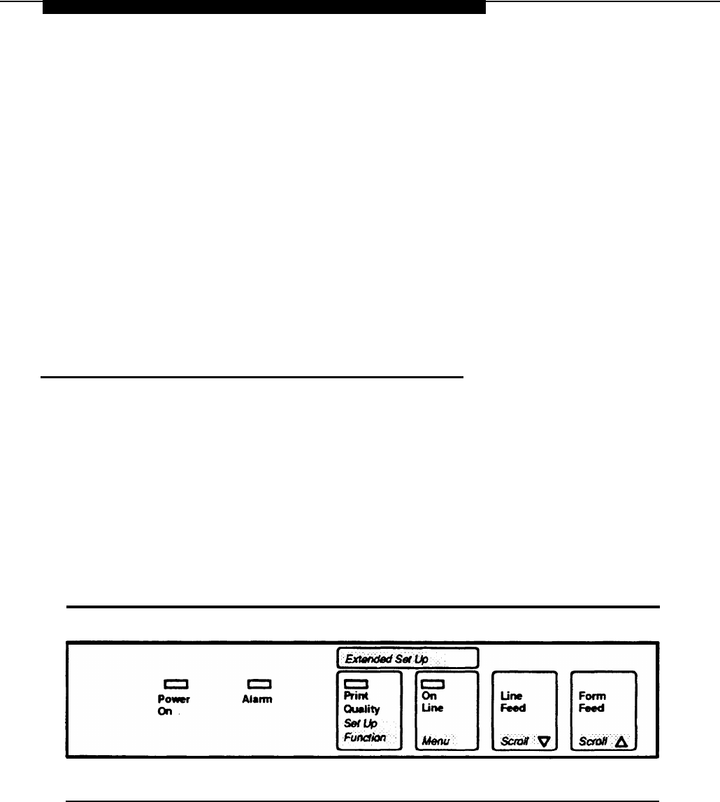
The switches and lamps have different meanings in Set Up Mode than
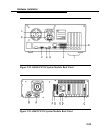
they do in NormalPrint Mode. The printer operation panel is shown in
Figure 2-36 with the setup functions identified.
Figure 2-36. Printer Operation Panel
2-61