


Hardware Installation
General Instructions
for Installing Circuit Boards
All expansion boards are installed according to the following general
instructions. The expansion slot to be used is described in the section on
preparing the individual boards.
Follow these steps to install an expansion board:
1.
2.
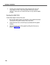
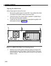
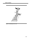
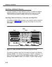
Refer to Figure 2-8. Remove the slot cover by removing the screw
(A)
from the metal cover
(B).
Then lift out the metal cover. Save the
screw to secure the board in place later. On the 6386 and 6386E
WGS processors, there may be a plastic cover over the slot as well
as the metal cover. If a plastic cover is present, break it out with the
screwdriver and discard it.
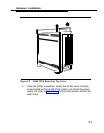
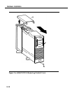
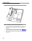
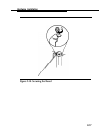
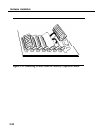
Holding the expansion board by its edges, insert the board into the
correct slot as shown in Figure 2-9.
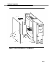
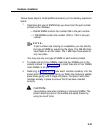
Be sure that the bracket on the expansion board is at the back of
the chassis (top of the chassis for floor models) and fits into the
space left by the slot cover. Be sure that the connector edge of the
board is properly aligned with the socket on the adapter board. The
front edge of long cards goes in the alignment guide attached near
the front (bottom on floor models) of the computer enclosure.
2-14