


Hardware Installation
3.
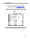
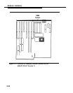
Each empty SIMM socket holds two SIMMs. For each socket,
insert the first SIMM into the left slot and the second SIMM into the
right slot.
4.
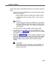
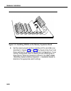
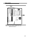
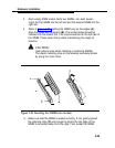
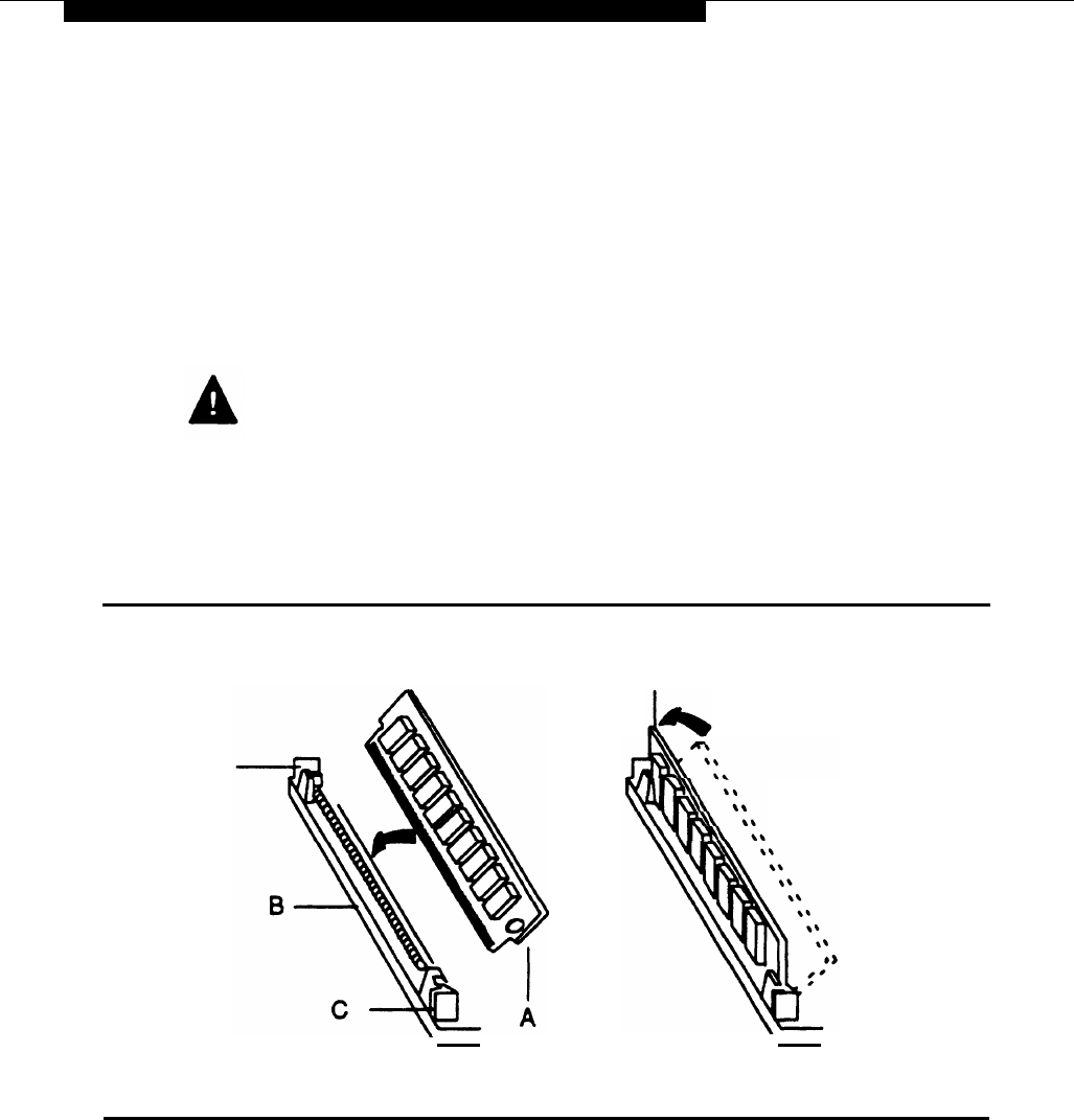
Refer to Figure 2-20. Holding the SIMM only by the edges
(A),
align the SIMM with its socket
(B).
The contact edge should be
inserted into the socket first. The chips should be on the left side of
the SIMM. Press down firmly while maintaining the angle of
insertion.
CAUTION:
Use extreme care when installing or removing SIMMs.
The plastic retaining clips on the sockets are easily broken
by using too much force.
c
D
Figure 2-20. Inserting the SIMMs into Sockets
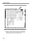
5.
Make sure that the SIMM is seated correctly. If not, gently spread
the retaining clips
(C)
just enough to permit the top edge of the
SIMM to be pulled away from the clips. Then reseat the SIMM.
2-29