


Hardware Installation
Connecting Peripherals and Cables
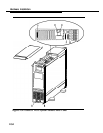
Before connecting peripherals and cables, close the system module case
by reversing the directions provided earlier for opening the case.
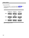
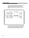
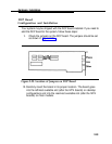
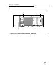
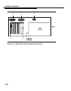
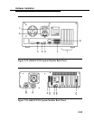
All peripherals and cables connect to the back panel of the system
module. The position of each connector is shown in Figures 2-30 through
2-34 for the various processors.
Refer to the appropriate figure while connecting the cables as follows:
1
2.
3.
4.
5.
6.
7.
Connect the line cord to the AC power-in socket
(A).
NOTE:
On the 6386E/33 WGS floor model, this socket is located at
the base of the system module in the rear. On the 6386E
WGS floor model, this socket is located on the back of the
power supply.
Connect one end of the video monitor power cord to the video
monitor and the other end to the monitor power outlet
(B).
NOTE:
On the 6386E/33 WGS floor model, this socket is located at
the base of the system module in the rear. On the 6386E
WGS floor model, this socket is located on the back of the
power supply.
Connect the video monitor signal cable to the VDC board
connector
(C).
Connect the keyboard to the keyboard interface port
(D).
Connect the mouse (if any) to the mouse port
(E).
Connect a parallel printer (if any) to the parallel port
(F).
Connect a remote access modem (if any) to serial port 1
(G).
2-50