


Advanced FEATURES of the M400E analyzer M400E Ozone Analyzer Operator’s Manual
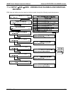
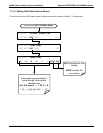
7.1.2. IDAS STRUCTURE
The iDAS is designed around the feature of a “record”. A record is a single data point. The type of date
recorded in a record is defined by two properties:
PARAMETER type that defines the kind of data to be stored (e.g. the average of O
3
concentrations
measured with three digits of precision). See Section 7.1.5.3.
A
TRIGGER event that defines when the record is made (e.g. timer; every time a calibration is performed,
etc.). See Section 7.1.5.2.
The sp
ecific
PARAMETERS and TRIGGER events that describe an individual record are defined in a construct
called a
DATA CHANNEL (see Section 7.1.5). Each data channel related one or more parameters with a
specific trigger event and various other operational characteristics related to the records being made (e.g. the
channels name, number or records to be made, time period between records, whether or not the record is
exported via the analyzer’s RS-232 port, etc.).
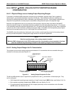
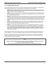
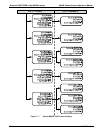
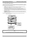
7.1.3. IDAS CHANNELS
The key to the flexibility of the iDAS is its ability to store a large number of combinations of triggering events and
data parameters in the form of data channels. Users may create up to 20 data channels and each channel can
contain one or more parameters. For each channel, the following are selected:
One triggering event is selected
Up to 50 data parameters, which can be the shared between channels.
Several properties that define the structure of the channel and allow the user to make operational
decisions regarding the channel.
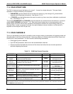
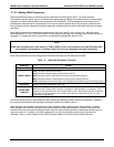
Table 7-2: iDAS Data Channel Properties
PROPERTY DESCRIPTION DEFAULT SETTING RANGE
NAME
The name of the data channel.
“NONE”
Up to 6 letters or digits
1.
TRIGGERING
EVENT
The event that triggers the data channel to
measure and store the datum
ATIMER
Any available event
(see Appendix A-5).
NUMBER AND
LIST OF
PARAMETERS
A User-configurable list of data types to be
recorded in any given channel.
1-DETMES
Any available parameter
(see Appendix A-5).
REPORT PERIOD
The amount of time between each channel data
point.
000:01:00
000:00:01 to
366:23:59
(Days:Hours:Minutes)
NUMBER OF
RECORDS
The number of reports that will be stored in the
data file. Once the limit is exceeded, the oldest
data is over-written.
100
1 to 1 million, limited by
available storage space.
RS-232 REPORT
Enables the analyzer to automatically report
channel values to the RS-232 ports.
OFF
OFF or ON
CHANNEL
ENABLED
Enables or disables the channel. Allows a channel
to be temporarily turned off without deleting it.
ON
OFF or ON
CAL HOLD OFF
Disables sampling of data parameters while
instrument is in calibration mode
2
.
OFF
OFF or ON
1
More with APICOM, but only the first six are displayed on the front panel).
2
When enabled records are not recorded until the DAS HOLD OFF period is passed after calibration mode. DAS HOLD OFF SET in
the VARS menu (see Section 6.12.)
78 04315 Rev. C1