


Theory of Operation M400E Ozone Analyzer Operator’s Manual
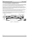
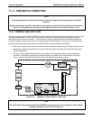
An analog signal is generated by an optical bench that includes the Photometer UV Lamp, the Absorption Tube
assembly and the UV Detector and Preamp. This signal constantly cycles between a voltage level
corresponding to concentration of O
3
in the measure gas and the one corresponding to the lack of O
3
in the
reference gas. This signal is transformed converted into digital data by a unipolar, analog-to-digital converter,
located on the motherboard.
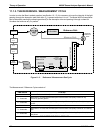
A variety of sensors report other critical operational parameters, again through the signal processing capabilities
of the motherboard. This data is used to calculate O
3
concentration and as trigger events for certain warning
messages and control commands issued by the CPU. They are stored in memory by the CPU and in most
cases can be viewed but the user via the front panel display.
The CPU communicates with the user and the outside world in a variety of manners:
Through the analyzer’s keyboard and vacuum florescent display over a clocked, digital, serial I/O bus
(using a protocol called I
2
C);
RS 232 & RS485 Serial I/O channels;
Various DCV and DCA analog outputs and;
Several sets of Digital I/O channels.
Finally, the CPU issues commands via a series of relays and switches (also over the I
2
C bus) located on a
separate printed circuit assembly, called the relay PCA, to control the function of key electromechanical devices
such as heaters and valves.
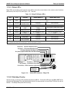
11.3.2. CPU
The Model 400E’s CPU is a, low power (5 VDC, 0.8A max), high performance, 386-based microcomputer
running MS-DOS. Its operation and assembly conform to the PC/104 Specification version 2.3 for embedded
PC and PC/AT applications. It has 2 MB of DRAM on board and operates at 40MHz over an internal 32-bit data
and address bus. Chip to chip data handling is performed by two 4-channel DMA devices over data busses of
either 8-bit or 16-bit configuration. The CPU supports both RS-232 and RS-485 Serial I/O.
The CPU includes two types of non-volatile data storage.
DISK ON CHIP: While technically an EEPROM, the Disk-on-Chip (DOC), this device appears to the CPU
as, behaves as and performs the same function in the system as an 8MB disk drive. It is used to store
the operating system for the computer, the T-API Firmware, and most of the operational data generated
by the analyzer’s Internal Data Acquisition System (iDAS - see Section 7.1).
FLASH CHIP: Another, smaller EEPROM used to store critical calibration and configuration data.
Segregating this data on a separate, less heavily accessed chip significantly decreases the chance of this
key data being corrupted.
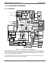
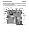
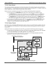
11.3.3. MOTHERBOARD
This printed Circuit assembly provides a multitude of functions including, A/D conversion, digital input/output,
PC-104 to I2C translation, temperature sensor signal processing and is a pass through for the RS-232 and RS-
485 signals.
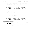
11.3.3.1. A to D Conversion
Analog signals, such as the voltages received from the analyzers various sensors, are converted into digital
signals that the CPU can understand and manipulate by the analog to digital converter (A/D). Under the control
of the CPU, this functional block selects a particular signal input and then coverts the selected voltage into a
digital word.
198 04315 Rev. C1