


M400E Ozone Analyzer Operator’s Manual Advanced FEATURES of the M400E analyzer
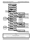
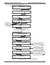
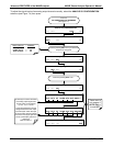
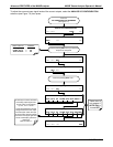
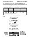
7.4.2.3. Manual Calibration of the Analog Outputs configured for Voltage Ranges
For highest accuracy, the voltages of the analog outputs can be manually calibrated.
NOTE:
The menu for manually adjusting the analog output signal level will only appear if the AUTO-CAL feature
is turned off for the channel being adjusted (See Section 7.4.2.1).
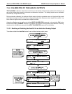
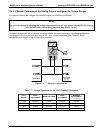
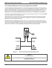
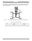
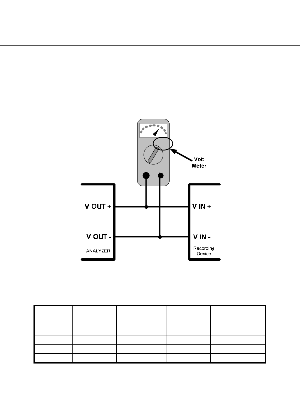
Calibration is performed with a voltmeter connected across the output terminals and by changing the actual
output signal level using the front panel keys in 100, 10 or 1 count increments. See Figure 3-7 for pin
assignm
ents and diagram of the analog output connector.
V
+DC Gnd
Figure 7-5: Setup for Calibrating An
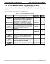
Table 7-7: Voltage Tolerances for the TEST CHANNEL Calibration
FULL
SCALE
ZERO
TOLERANCE
SPAN VOLTAGE
SPAN
TOLERANCE
MINIMUM
ADJUSTMENT
(1 count)
0.1 VDC ±0.0005V 90 mV ±0.001V 0.02 mV
1 VDC ±0.001V 900 mV ±0.001V 0.24 mV
5 VDC ±0.002V 4500 mV ±0.003V 1.22 mV
10 VDC ±0.004V 4500 mV ±0.006V 2.44 mV
04315 Rev. C1 103