M400E Ozone Analyzer Operator’s Manual Table of Contents
TABLE OF CONTENTS
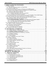
GENERAL INFORMATION .................................................................................. 1
1. INTRODUCTION .................................................................................................................. 3
1.1. Safety Messages............................................................................................................................................3
1.2. M400E Overview............................................................................................................................................4
1.3. Using This Manual .........................................................................................................................................5
2. SPECIFICATIONS, APPROVALS AND WARRANTY ......................................................... 7
2.1. Specifications.................................................................................................................................................7
2.2. EPA Equivalency Designation .......................................................................................................................9
2.3. CE Mark Compliance .....................................................................................................................................9
2.4. Warranty.......................................................................................................................................................10
3. GETTING STARTED .......................................................................................................... 11
3.1. Model 400E Analyzer Layout.......................................................................................................................11
3.2. Unpacking the M400E analyzer...................................................................................................................15
3.2.1.1. Ventilation Clearance .....................................................................................................................16
3.3. Electrical Connections .................................................................................................................................16
3.3.1. Power Connection..................................................................................................................................16
3.3.2. Analog Output Connections...................................................................................................................17
3.3.3. Connecting the Status Outputs..............................................................................................................18
3.3.4. Connecting the Control Inputs ...............................................................................................................19
3.3.5. Connecting the Serial Ports ...................................................................................................................20
3.3.6. Connecting to a LAN or the Internet ......................................................................................................20
3.3.7. Connecting to a Multidrop Network........................................................................................................20
3.4. Pnenumatic Connections .............................................................................................................................21
3.4.1. About Zero Air and Calibration Gas.......................................................................................................21
3.4.2. Basic Pneumatic Setup for the M400E analyzer ...................................................................................22
3.4.3. Pneumatic Setup for the M400E Analyzer with Internal Zero/Span Option (IZS) .................................23
3.4.4. Pneumatic Setups for Ambient Air Monitoring with the M400E analyzer ..............................................24
3.4.4.1. Pneumatic Set Up for M400E’s Located in the Same Room Being Monitored..............................24
3.4.4.2. Pneumatic Set Up for M400E’s Monitoring Remote Locations......................................................25
3.5. Initial Operation............................................................................................................................................26
3.5.1. Start Up..................................................................................................................................................26
3.5.2. Warm Up................................................................................................................................................27
3.5.3. Warning Messages ................................................................................................................................27
3.5.4. Functional Check ...................................................................................................................................29
3.6. Initial Calibration of the M400E Analyzer....................................................................................................30
3.6.1. Interferents for O
3
Measurement ...........................................................................................................30
3.6.2. Initial Calibration Procedure for M400E analyzers without Options ......................................................31
3.6.2.1. Verifying the M400E Reporting Range Settings.............................................................................31
3.6.2.2. Verify the Expected O
3
Span Gas Concentration:..........................................................................32
3.6.2.3. Initial Zero/Span Calibration Procedure: ........................................................................................33
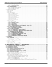
3.7. Configuring the Internal Zero/Span Option (IZS).........................................................................................34
3.7.1. Verify the O
3
Generator and Expected O
3
Span Concentration Settings:.............................................34
3.7.2. Setting the O
3
Generator Low-Span (Mid Point) Output Level ..............................................................35
3.7.3. Turning on the Reference Detector Option............................................................................................36
3.7.4. Initial Calibration and Conditioning OF M400E analyzers with the IZS Option Installed.......................37
3.7.4.1. Initial O
3
Scrubber Conditioning .....................................................................................................37
3.7.4.2. Verifying the M400E Reporting Range Settings.............................................................................38
3.7.4.3. Initial Zero/Span Calibration Procedure: ........................................................................................38
3.7.4.4. Initiate Daily Zero-Point Auto-Cal of M400E’s Monitoring Low Levels of O
3
..................................38
4. FREQUENTLY ASKED QUESTIONS AND GLOSSARY .................................................. 41
4.1. FAQ’s ...........................................................................................................................................................41
4.2. Glossary.......................................................................................................................................................43
04315 Rev. C1 i


