Table of Contents M400E Ozone Analyzer Operator’s Manual
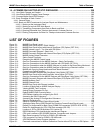
13. GENERAL TROUBLESHOOTING & REPAIR OF THE M400E ANALYZER................ 233
13.1. General Troubleshooting ........................................................................................................................ 233
13.1.1. Fault Diagnosis with WARNING Messages...................................................................................... 234
13.1.2. Fault Diagnosis With Test Functions ................................................................................................ 236
13.1.3. DIAG SIGNAL I/O: Using the Diagnostic Signal I/O Function .................................................... 237
13.2. Using the Analog Output Test Channel.................................................................................................. 239
13.3. Using the Internal Electronic Status LEDs.............................................................................................. 240
13.3.1. CPU Status Indicator ........................................................................................................................ 240
13.3.2. Relay PCA Status LED s .................................................................................................................. 240
13.3.2.1. I
2
C Bus Watchdog Status LEDs ................................................................................................ 240
13.3.2.2. O
3
Option Status LED s............................................................................................................. 241
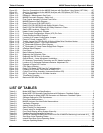
13.4. Gas Flow Problems ................................................................................................................................ 242
13.4.1. Typical Flow Problems...................................................................................................................... 242
13.4.1.1. Flow is Zero ............................................................................................................................... 242
13.4.1.2. Low Flow ................................................................................................................................... 242
13.4.1.3. High Flow................................................................................................................................... 243
13.4.1.4. Actual Flow Does Not Match Displayed Flow ........................................................................... 243
13.4.1.5. Sample Pump............................................................................................................................ 243
13.5. Calibration Problems .............................................................................................................................. 243
13.5.1. Mis-Calibrated................................................................................................................................... 243
13.5.2. Non-Repeatable Zero and Span....................................................................................................... 243
13.5.3. Inability to Span – No Span Key (CALS) .......................................................................................... 244
13.5.4. Inability to Zero – No Zero Key (CALZ) ............................................................................................ 244
13.6. Other Performance Problems................................................................................................................. 244
13.6.1. Temperature Problems ..................................................................................................................... 244
13.6.1.1. Box Temperature....................................................................................................................... 244
13.6.1.2. Sample Temperature................................................................................................................. 244
13.6.1.3. UV Lamp Temperature.............................................................................................................. 245
13.6.1.4. IZS Ozone Generator Temperature (Optional) ......................................................................... 245
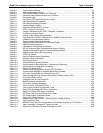
13.7. Subsystem Checkout.............................................................................................................................. 246
13.7.1. AC Main Power................................................................................................................................. 246
13.7.2. DC Power Supply.............................................................................................................................. 246
13.7.3. I
2
C Bus.............................................................................................................................................. 247
13.7.4. Keyboard/Display Interface............................................................................................................... 248
13.7.5. Relay PCA ........................................................................................................................................ 248
13.7.6. Photometer Pressure /Flow Sensor Assembly................................................................................. 249
13.7.7. Motherboard...................................................................................................................................... 250
13.7.7.1. Test Channel / Analog Outputs Voltage.................................................................................... 250
13.7.7.2. A/D Functions............................................................................................................................ 251
13.7.7.3. Status Outputs........................................................................................................................... 251
13.7.7.4. Control Inputs ............................................................................................................................ 252
13.7.8. CPU .................................................................................................................................................. 252
13.7.9. RS-232 Communications.................................................................................................................. 253
13.7.9.1. General RS-232 Troubleshooting.............................................................................................. 253
13.7.9.2. Troubleshooting Analyzer/Modem or Terminal Operation ........................................................ 253
13.8. Trouble Shooting the photometer........................................................................................................... 254
13.8.1. Checking Measure / Reference Valve .............................................................................................. 254
13.8.2. Checking The Photometer UV Lamp Power Supply......................................................................... 254
13.9. Trouble Shooting the IZS Options O
3
generator..................................................................................... 255
13.9.1. Checking The O
3
Generator UV Lamp Power Supply...................................................................... 255
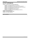
13.10. Repair Procedures ............................................................................................................................... 256
13.10.1. Repairing Sample Flow Control Assembly ..................................................................................... 256
13.10.2. Replacing The Standard Reference O
3
Scrubber .......................................................................... 257
13.10.3. Replacing the IZS O
3
Scrubber ...................................................................................................... 257
13.10.4. Metal Wool Scrubber Option........................................................................................................... 258
13.10.5. Disk-On-Chip Replacement Procedure .......................................................................................... 258
13.11. Technical Assistance............................................................................................................................ 258
vi 04315 Rev. C1


