


Theory of Operation M400E Ozone Analyzer Operator’s Manual
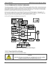
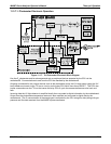
11.3.7.2. O
3
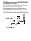
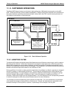
Photometer UV Lamp Power Supply
The photometer’s UV lamp requires a high voltage AC supply voltage to create and maintain its mercury vapor
plasma arc. This AC voltage is produced by a variable transformer, the primary of which is supplied by the
output of a DC regulator (powered by the instrument’s +15 VDC supply). A circuit made up of a control IC and
several FET’s, turns the transformer on and off converting it into a 30kHz square wave.
The DC regulator is controlled by a drive voltage supplied by an amplifier that adjusts its output based on the
difference between the rectified current output of the lamp and a constant voltage resulting from a D-to-A
converted “set-point” signal sent by the CPU via the I
2
C bus. If the rectified current output by the lamp is lower
than the CPU set point voltage, the amplifier drives the regulator output voltage higher. If the current output is
higher than the set point voltage, the amplifier decreases the regulator output voltage.
At start up, when there is no mercury vapor arc and therefore no current being output by the lamp, the amplifier
continues to drive the regulator output (and therefore the transformer output) higher and higher until the mercury
is vaporized and the plasma arc is created (about 800 VAC). Once the arc is created, current begins to flow and
the error amplifier reduces the regulator/transformer output to a steady 200 VAC.
.
Figure 11-18: O
3
Photometer UV Lamp Power Supply Block Diagram
212 04315 Rev. C1