


M400E Ozone Analyzer Operator’s Manual 357BRemote Operation Of The M400E
8. REMOTE OPERATION OF THE M400E
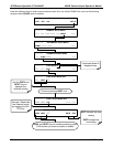
8.1. USING THE ANALYSER’S COMMUNICATION PORTS
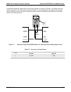
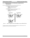
The M400E is equipped with two serial communication ports located on the rear panel accessible via two DB-9
connectors on the back panel of the instrument (See Figure 3-2). The COM1 connector is a male DB-9
con
nector and the COM2 is a female DB9 connector.
Both ports operate similarly and give the user the ability to communicate with, issue commands to, and receive
data from the analyzer through an external computer system or terminal.
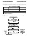
The RS-232 port (COM1) can also be configured to operate in single or RS-232 multidrop mode (option
62; See Section 5.7.2 and 8.2.1).
The COM2 port can be configured for standard RS-232 operation, half-duplex RS-485 communication or
for access via an LAN by installing the Teledyne Instruments Ethernet interface card (See Section 5.7.3
and 8.4).
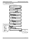
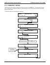
8.1.1. RS-232 DTE AND DCE COMMUNICATION
RS-232 was developed for allowing communications between data terminal equipment (DTE) and data
communication equipment (DCE). Basic data terminals always fall into the DTE category whereas modems are
always considered DCE devices.
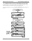
Electronically, the difference between the DCE and DTE is the pin assignment of the Data Receive and Data
Transmit functions.
DTE devices receive data on pin 2 and transmit data on pin 3.
DCE devices receive data on pin 3 and transmit data on pin 2.
A switch located below the serial ports on the rear panel allows the user to switch between DTE (for use with
data terminals) or DCE (for use with modems). Since computers can be either DTE or DCE, check your
computer to determine which mode to use.
04315 Rev. C1 115