


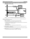
M400E Ozone Analyzer Operator’s Manual Getting Started
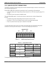
3.3.4. CONNECTING THE CONTROL INPUTS
The analyzer is equipped with three digital control inputs that can be used to activate the zero and span
calibration modes remotely (see Section9.2).
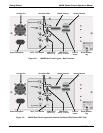
Acce
ss to these inputs is provided via an 8-pin connector labeled CONTROL IN on the analyzer’s rear panel
(See Figure 3-2).
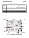
Table 3-6:
Control Input Pin Assignments
Input #
Status
Definition
ON Condition
A
REMOTE
ZERO CAL
The Analyzer is placed in Zero Calibration mode. The mode field of
the display will read ZERO CAL R.
B
REMOTE
LO SPAN CAL
The Analyzer is placed in Lo Span Calibration mode. The mode field
of the display will read LO CAL R.
C
REMOTE
SPAN CAL
The Analyzer is placed in Span Calibration mode. The mode field of
the display will read SPAN CAL R.
D, E & F Spare
Digital Ground
The ground level from the analyzer’s internal DC Power Supplies
(same as chassis ground).
U
External Power
input
Input pin for +5 VDC required to activate pins A – F.
+
5 VDC output
Internally generated 5V DC power. To activate inputs A – F, place a
jumper between this pin and the “U” pin. The maximum amperage
through this port is 300 mA (combined with the analog output supply,
if used).
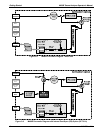
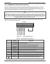
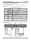
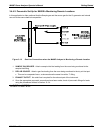
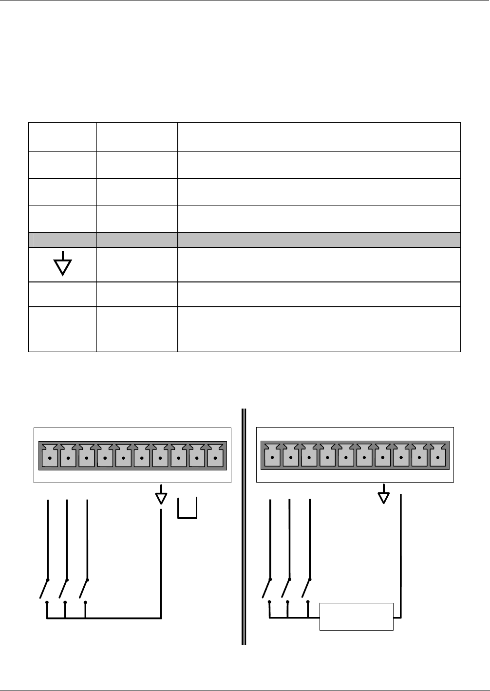
There are two methods for energizing the Control Inputs. The internal +5V available from the pin labeled “+” is
the most convenient method however, to ensure that these inputs are truly isolated; a separate external 5 VDC
power supply should be used.
CONTROL IN
A B C D E F U
+
LO SPAN
ZERO
SPAN
CONTROL IN
A B C D E F U
+
LO SPAN
ZERO
SPAN
-
+
5 VDC Power
Supply
Local Power Connections
External Power Connections
Figure 3-9: Energizing the M400E Control Inputs
04315 Rev. C1 19