


M400E Ozone Analyzer Operator’s Manual 357BRemote Operation Of The M400E
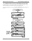
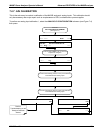
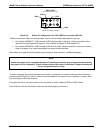
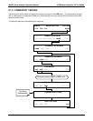
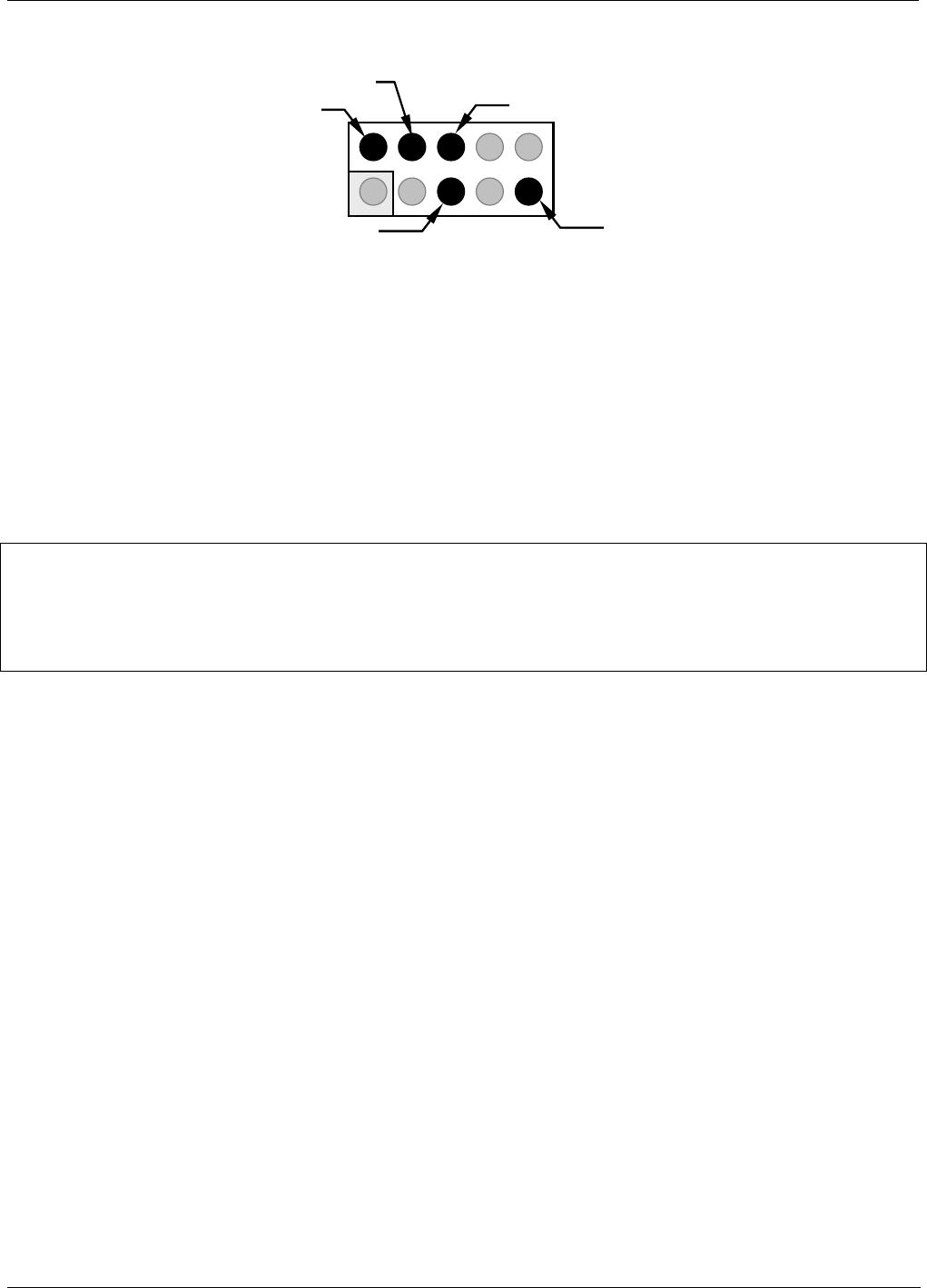
CN3 & CN4
(Located on CPU card)
(As seen from inside analyzer)
TXD
GND
246810
135 7 9
RXD
RTS
CTS
Figure 8-2: Defaul Pin Assignments for CPU COM Port connector (RS-232).
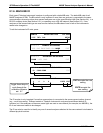
Teledyne Instruments offers two mating cables, one of which should be applicable for your use.
Part number WR000077, a DB-9 female to DB-9 female cable, 6 feet long. Allows connection of the
serial ports of most personal computers. Also available as Option 60 (See Section 5.7).
Part number WR000024, a DB-9 female to DB-25 male cable. Allows connection to the most common
styles of modems (e.g. Hayes-compatible) and code activated switches.
Both cables are configured with straight-through wiring and should require no additional adapters.
NOTE
Cables that appear to be compatible because of matching connectors may incorporate internal wiring
that makes the link inoperable. Check cables acquired from sources other than Teledyne Instruments
for pin assignments before using.
To assist in properly connecting the serial ports to either a computer or a modem, there are activity indicators
just above the RS-232 port. Once a cable is connected between the analyzer and a computer or modem, both
the red and green LEDs should be on.
If the lights are not lit, use small switch on the rear panel to switch it between DTE and DCE modes
If both LEDs are still not illuminated, make sure the cable properly constructed.
04315 Rev. C1 117