


Basic Operation of the M400E Analyzer M400E Ozone Analyzer Operator’s Manual
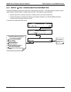
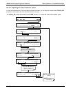
6.4. SETUP MODE
The SETUP mode contains a variety of choices that are used to configure the analyzer’s hardware and software
features, perform diagnostic procedures, gather information on the instruments performance and configure or
access data from the internal data acquisition system (iDAS).
For a visual representation of the software menu trees, refer to Appendix A-1.
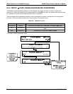
The areas accessed under the SETUP mode are:
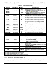
Table 6-4: Primary Setup Mode Features and Functions
MODE OR FEATURE
KEYPAD
LABEL
DESCRIPTION
MANUAL
SECTION
Analyzer Configuration
CFG
Lists key hardware and software configuration information 6.4.1
Auto Cal Feature
ACAL
Used to set up and operate the AutoCal feature.
Only appears if the analyzer has one of the calibration valve
options installed (see Section 5.6).
9.4
Internal Data Acquisition
(iDAS)
DAS
Used to set up the iDAS system and view recorded data 7.1
Analog Output Reporting
Range Configuration
RNGE
Used to configure the output signals generated by the
instruments analog outputs.
6.4.4
Calibration Password Security
PASS
Turns the calibration password feature ON/OFF 6.4.2
Internal Clock Configuration
CLK
Used to Set or adjust the instrument’s internal clock 6.4.3
Advanced SETUP features MORE
This button accesses the instruments secondary setup menu
See
Table 6-5
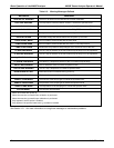
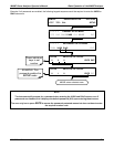
Table 6-5: Secondary Setup Mode Features and Functions
MODE OR FEATURE
KEYPAD
LABEL
DESCRIPTION
MANUAL
SECTION
External Communication
Channel Configuration
COMM
Used to set up and operate the analyzer’s various external I/O
channels including RS-232; RS-485, modem communication
and/or Ethernet access.
8
System Status Variables
VARS
Used to view various variables related to the instruments current
operational status
Changes made to any variable are not acknowledged and
recorded in the instrument’s memory until the ENTR key is
pressed.
Pressing the EXIT key ignores the new setting.
If the EXIT key is pressed before the ENTR key, the analyzer
will beep alerting the user that the newly entered value has
been lost.
7.2
System Diagnostic Features
and
Analog Output Configuration
DIAG
Used to access a variety of functions that are used to configure,
test or diagnose problems with a variety of the analyzer’s basic
systems.
Most notably, the menus used to configure the output signals
generated by theinstruments’ analog outputs are located here.
7.3 & 7.4
64 04315 Rev. C1