


General Troubleshooting & Repair of the M400E Analyzer M400E Ozone Analyzer Operator’s Manual
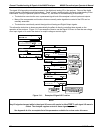
13.7. SUBSYSTEM CHECKOUT
13.7.1. AC MAIN POWER
The M400E analyzer’s electronic systems will operate with any of the specified power regimes. As long as
system is connected to 100-120 VAC or 220-240 VAC at either 50 or 60 Hz it will turn on and after about 30
seconds show a front panel display.
Internally, the status LEDs located on the Relay PCA, Motherboard and CPU should turn on as soon as
the power is supplied.
If they do not, check the circuit breaker built into the ON/OFF switch on the instruments front panel
The analyzer is correctly configured for the AC mains voltage in use if:
The Sample Pump is running.
If incorrect power is suspected, check that the correct voltage and frequency is present at the line input on the
rear panel.
Verify that the pump power configuration plug is properly wired (see Section 11.3.6.1)
If the unit is set for 230 VAC and is plugged into 115 VAC or 100 VAC the sample pump will not start.
If the unit is set for 115 or 100 VAC and is plugged into a 230 VAC circuit, the circuit breaker built into the
ON/OFF Switch on the front panel will trip to the OFF position immediately after power is switched on.
CAUTION
Electrical Shock Hazard
Should the AC power circuit breaker trip, investigate and correct the condition
causing this situation before turning the analyzer back on.
13.7.2. DC POWER SUPPLY
If you have determined that the analyzer’s AC mains power is working, but the unit is still not operating properly,
there may be a problem with one of the instrument’s switching power supplies. The supplies can have two
faults, namely no DC output, and noisy output.
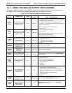
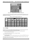
To assist tracing DC Power Supply problems, the wiring used to connect the various printed circuit assemblies
and DC Powered components and the associated test points on the relay PCA follow a standard color-coding
scheme as defined in the following table.
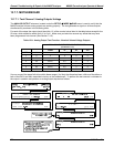
Table 13-6: DC Power Test Point and Wiring Color Codes
NAME TEST POINT# COLOR DEFINITION
DGND
1
Black Digital ground
+5V
2
Red
AGND
3
Green Analog ground
+15V
4
Blue
-15V
5
Yellow
+12R
6
Purple 12 V return (ground) line
+12V
7
Orange
246 04315 Rev. C1