


General Troubleshooting & Repair of the M400E Analyzer M400E Ozone Analyzer Operator’s Manual
13.7.7. MOTHERBOARD
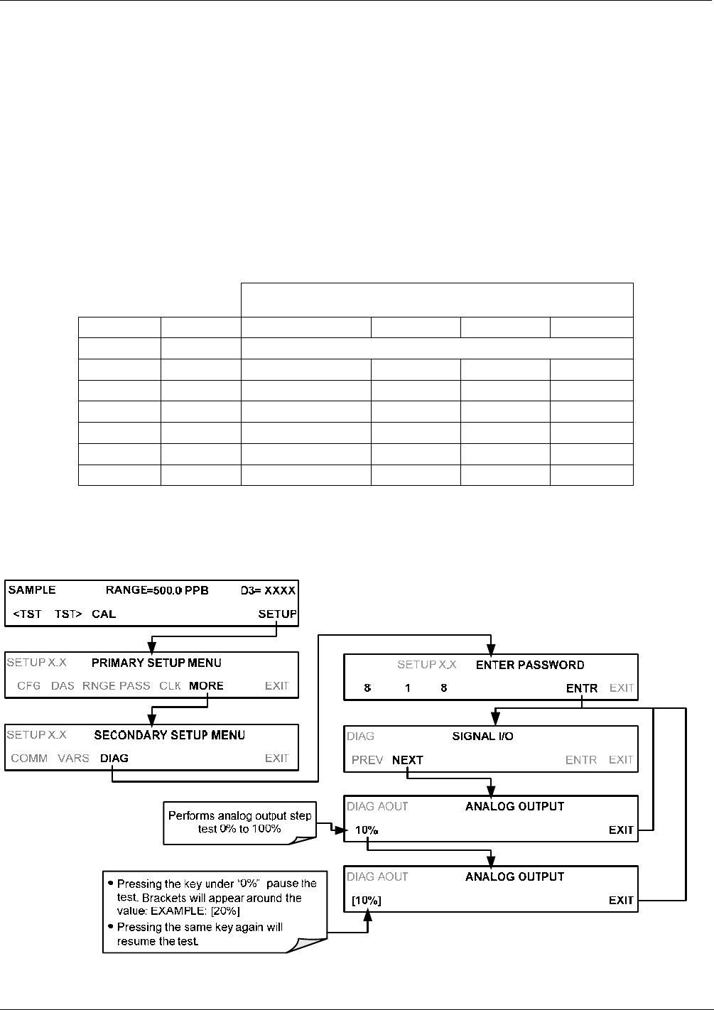
13.7.7.1. Test Channel / Analog Outputs Voltage
The ANALOG OUTPUT submenu, located under the SETUP MORE DIAG menu is used to verify that the
M400E analyzer’s three analog outputs are working properly. The test generates a signal on all three outputs
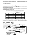
simultaneously as shown in the following table:
For each of the steps the output should be within 1% of the nominal value listed in the table below except for the
0% step, which should be within 0mV ±2 to 3 mV. Make sure you take into account any offset that may have
been programmed into channel (See Section 7.4.5).
Table 13-9: Analog Output Test Function - Nominal Values Voltage Outputs
FULL SCALE OUTPUT OF VOLTAGE RANGE
(see Section 7.4.3)
100MV 1V 5V 10V
STEP % NOMINAL OUTPUT VOLTAGE
1 0 0 0 0 0
2 20 20 mV 0.2 1 2
3 40 40 mV 0.4 2 4
4 60 60 mV 0.6 3 6
5 80 80 mV 0.8 4 8
6 100 100 mV 1.0 5 10
If one or more of the steps fails to be within these ranges, it is likely that there has been a failure of the either or
both of the DACs and their associated circuitry on the motherboard. To perform the test connect a voltmeter to
the output in question and perform an analog output step test as follows:
250 04315 Rev. C1