


Getting Started M400E Ozone Analyzer Operator’s Manual
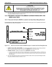
CAUTION
General Safety Hazard
VENTING SHOULD BE OUTSIDE THE SHELTER OR IMMEDIATE AREA
SURROUNDING THE INSTRUMENT AND CONFORM TO ALL SAFETY
REQUIREMENTS REGARDING EXPOSURE TO O
3
.
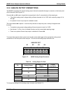
4. Once the appropriate pneumatic connections have been made, check all pneumatic fittings for leaks
using the procedures defined in Section 12.3.4.
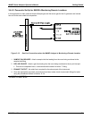
3.4.4. PNEUMATIC SETUPS FOR AMBIENT AIR MONITORING WITH THE
M400E ANALYZER
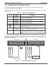
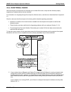
3.4.4.1. Pneumatic Set Up for M400E’s Located in the Same Room Being Monitored.
In this application is often preferred that the sample gas and the source gas for the O
3
generator and internal
zero air be the same chemical composition.
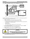
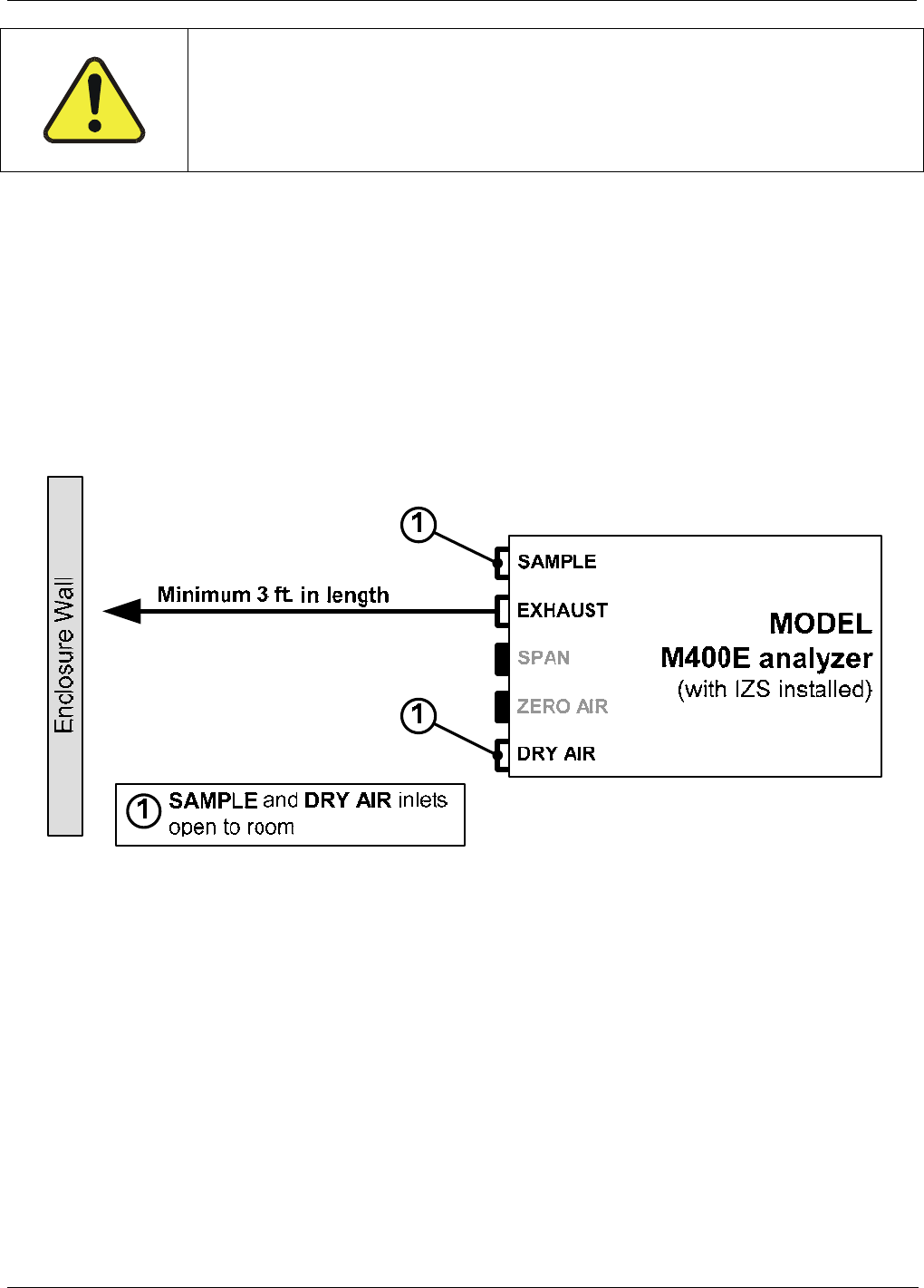
Figure 3-12: Gas Line Connections when the M400E Analyzer is Located in the Room Being Monitored
1. SAMPLE GAS & DRY AIR SOURCES: For instruments located in the same room, being monitored
there is no need to attach the gas inlet lines to the SAMPLE inlet or the dry air inlet.
2. EXHAUST OUTLET: Attach an outlet line to the EXHAUST outlet fitting.
In order to prevent the instrument from re-breathing its own exhaust gas (resulting in artificially low
readings) the end of the exhaust outlet line should be located at least 2 feet from the back panel of
the instrument.
3. Once the appropriate pneumatic connections have been made, check all pneumatic fittings for leaks
using the procedures defined in Section 12.3.4.
24 04315 Rev. C1