


M400E Ozone Analyzer Operator’s Manual Theory of Operation
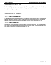
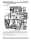
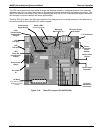
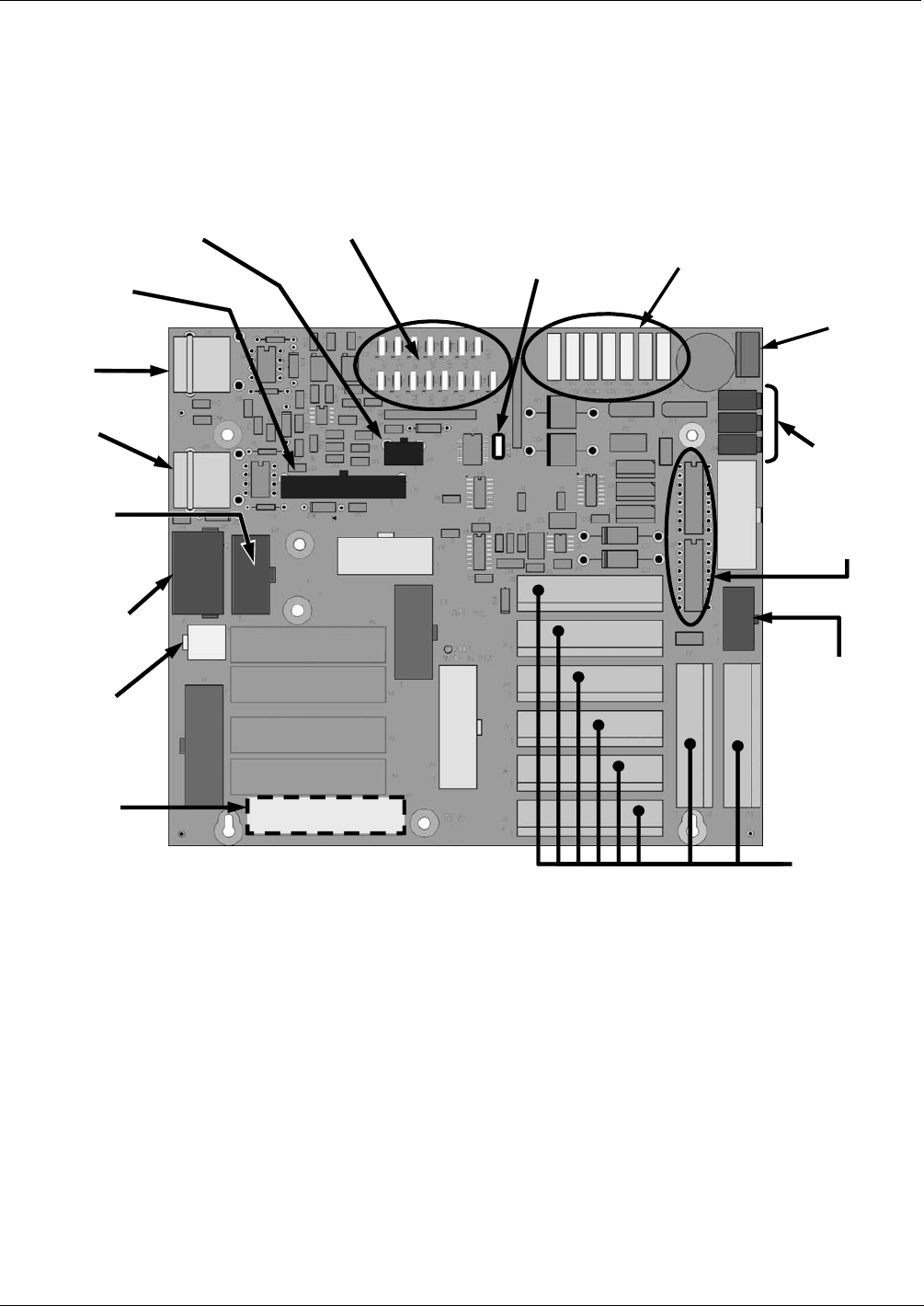
The CPU issues commands via a series of relays and switches located on a separate printed circuit assembly,
called the relay PCA, to control the function of key electromechanical devices such as heaters and valves. The
relay PCA receives instructions in the form of digital signals over the I
2
C bus, interprets these digital instructions
and activates its various switches and relays appropriately.
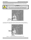
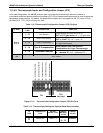
The relay PCA is located in the right-rear quadrant of the analyzer and is mounted vertically on the backside of
the same bracket as the instrument’s DC power supplies.
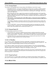
Power
Connection
for DC
Heaters
Status LED’s
(D2 through D16)
DC Power Supply
Test Points
Watchdog
Status LED (D1)
(JP5)
Thermocouple
Configuration
Jumpers
Thermocouple
Signal Output
I
2
C Connector
V
alve Control
Drivers
Pump Power
Output
(JP7)
Pump AC
Configuration
Jumper
AC Power
IN
DC Power
Distribution
Connectors
V
alve Control
Connector
(J15)
TC1 Input
(J16)
TC2 Input
AC Relay
(
Only present if optional.
Metal Wool Scrubber
installed)
Figure 11-6: Relay PCA Layout (P/N 04523-0100)
04315 Rev. C1 201