


Theory of Operation M400E Ozone Analyzer Operator’s Manual
11.2. PNEUMATIC OPERATION
NOTE
It is important that the sample airflow system is both leak tight and not pressurized over ambient
pressure.
Regular leak checks should be performed on the analyzer as described in the maintenance schedule,
Table 12-2. Procedures for correctly performing leak checks can be found in Section 12.3.4.
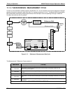
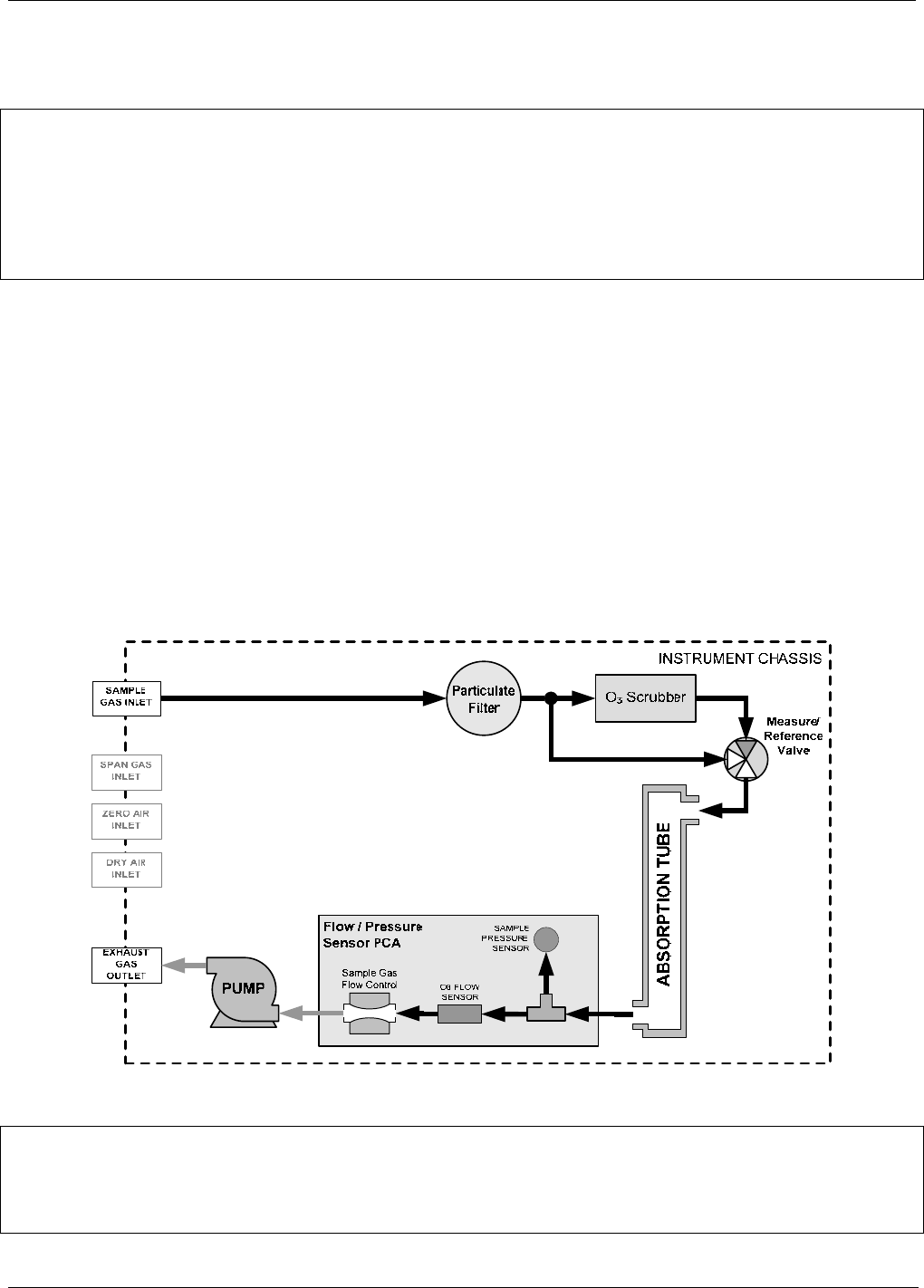
11.2.1. SAMPLE GAS AIR FLOW
The flow of sample gas through the M400E analyzer is produced by an internal pump that draws a small vacuum
on the downstream side of a critical flow orifice thereby creating a controlled airflow through the analyzers
absorption tube and other components. This requires the analyzer gas inlets be at or near ambient pressure
usually managed by placing a vent line on the incoming gas line (see Figure 3-10, Figure 3-11 and Figure 5-5).
By placing th
e pump down stream from the sample chamber, several problems are avoided.
First, the pumping process heats and compresses the sample air complicating the measurement process.
Additionally, certain physical parts of the pump itself are made of materials that might chemically react
with the sample gas.
Finally, in certain applications where the concentration of the target gas might be high enough to be
hazardous, maintaining a negative gas pressure relative to ambient means that should a minor leak
occur, no sample gas would be pumped into the atmosphere surrounding analyzer.
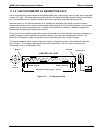
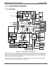
Figure 11-3: M400E Pneumatic Diagram – Basic Unit
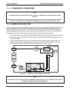
Note
For illustrations of the gas flow path for the M400E analyzer with the various calibration valve options
installed, see Figures Figure 3-6 and Figure 5-3.
194 04315 Rev. C1