


M400E Ozone Analyzer Operator’s Manual Theory of Operation
11.3. ELECTRONIC OPERATION
11.3.1. OVERVIEW
Serial I/O Ports
INTERNAL
PUMP
PHOTOMETER
IZS O
3
Generator
(optional)
Analog Outputs
Aout 1
Aout 4
Analog Outputs
(D/A)
External Digital I/O
Power Up
Circuit
Sensor Inputs
P
C
1
0
4
B
u
s
PC 104
CPU Card
Disk on
Chip
Flash
Chip
COM
1
COM
2
Aout 3
Aout 2
TEST CHANNEL OUTPUT
Status
Outputs
1 - 8
Control
Outputs
1 – 6
RS-232
or RS-485
RS-232
CPU
Status
LED
O
3
Generator
Reference
Detector
I
2
C Bus
Keyboard
& Display
Photometer
Lamp Heater
Optional IZS
O
3
Generator
Lamp Heater
O
3
Generator
Lamp Supply
Thermistor Interface
Box
Temperature
Gas Pressure
Sensor
Gas Flow Sensor
UV
Lamp
A/D
Converter
SPAN Valve
IZS
Sample/Cal
Valve
(Optional)
ZERO Valve
RELAY
PCA
I
2
C
Status
LED
Photometer
UV Lamp
Temperature
IZS Option O
3
Generator’s
UV Lamp Temperature
Photometer
Sample Gas
Temperature
Photometer
Lamp Power
Supply
Photometer
Detector
Preamp
Absorption tube
Photometer
Detector
O
3
Concentration RANGE2
O
3
Concentration RANGE1
Measure/
Reference
Valve
Optional
Ethernet
Card
Optional
Multidrop
Card
MOTHERBOARD
Optional Metal Wool Scrubber
Thermocouple Sensor
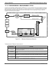
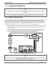
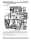
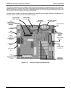
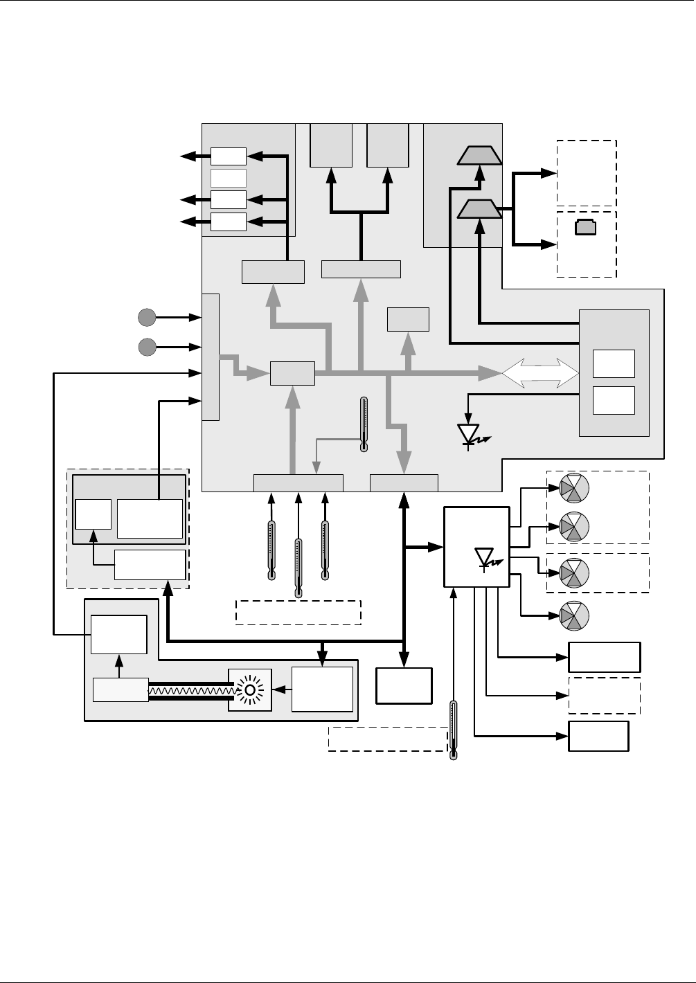
Figure 11-5: M400E Electronic Block Diagram
At its heart, the analyzer is a microcomputer (CPU) that controls various internal processes, interprets data,
makes calculations, and reports results using specialized firmware developed by T-API. It communicates with
the user as well as receives data from and issues commands to a variety of peripheral devices via a separate
printed circuit assembly called the motherboard.
The motherboard collects data, performs signal conditioning duties and routs incoming and outgoing signals
between the CPU and the analyzers other major components.
04315 Rev. C1 197