


General Troubleshooting & Repair of the M400E Analyzer M400E Ozone Analyzer Operator’s Manual
13.7.4. KEYBOARD/DISPLAY INTERFACE
The front panel keyboard, display and Keyboard Display Interface PCA can be verified by observing the
operation of the display when power is applied to the instrument and when a key is pressed on the front panel.
Assuming that there are no wiring problems and that the DC power supplies are operating properly:
The vacuum fluorescent display is good if on power-up a “-“ character is visible on the upper left hand
corner of the display.
If there is no “-“ character on the display at power-up and D1 on the Relay PCA or D2 on the valve driver
PCA is flashing then the Keyboard/Display Interface PCA is bad.
The CPU Status LED, DS5, is flashing, but there is no “-“ character on the display at power-up
If the analyzer starts operation with a normal display but pressing a key on the front panel does not
change the display, then there are three possible problems.
1. One or more of the keys is bad,
2. The interrupt signal between the Keyboard Display interface and the motherboard is broken, or
3. The Keyboard Display Interface PCA is bad.
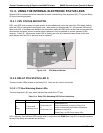
13.7.5. RELAY PCA
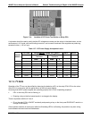
The Relay PCA can be most easily checked by observing the condition of the status LEDs on the Relay PCA
(see Section 13.3.2), and using the
SIGNAL I/O submenu under the DIAG menu (see Section 13.1.3) to toggle
each LED
ON or OFF.
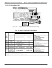
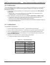
If D1 on the Relay PCA is flashing and the status indicator for the output in question (Heater power, Valve Drive,
etc.) toggles properly using the Signal I/O function, then the associated control device on the Relay PCA is bad.
Several of the control devices are in sockets and can be easily replaced. The table below lists the control device
associated with a particular function.
Table 13-8: Relay PCA Control Devices
FUNCTION
CONTROL
DEVICE
IN SOCKET
UV Lamp Heater Q2 No
Optional IZSO
3
Gen
Heater
Q3 No
Optional Metal Wool
Scrubber
K1 Yes
All Valves U5 Yes
248 04315 Rev. C1