


M400E Ozone Analyzer Operator’s Manual Getting Started
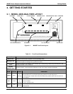
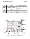
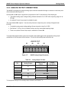
Table 3-2: M400E Analyzer Gas Inlet/Outlet Nomenclature
REAR PANEL
LABEL
FUNCTION CONFIGURATION VARIATIONS
SAMPLE
Connect the source of sample gas here.
Calibration gasses are also inlet here on:
Base configuration and;
Analyzers with the internal zero/span valve
option installed (OPT-51A)
EXHAUST
Connect exhaust gas line here (must be <10
meters).
All configurations
SPAN
Connect the source of calibrated span gas here. Only present with Zero/Span valves (OPT-50A)
ZERO AIR
Connect the source of zero air here. Only present with Zero/Span valves (OPT-50A)
DRY AIR
Attach the source of dry air here (< -20ºc dew
point).
Only present with the internal zero/span option
(OPT-51A)
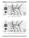
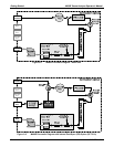
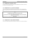
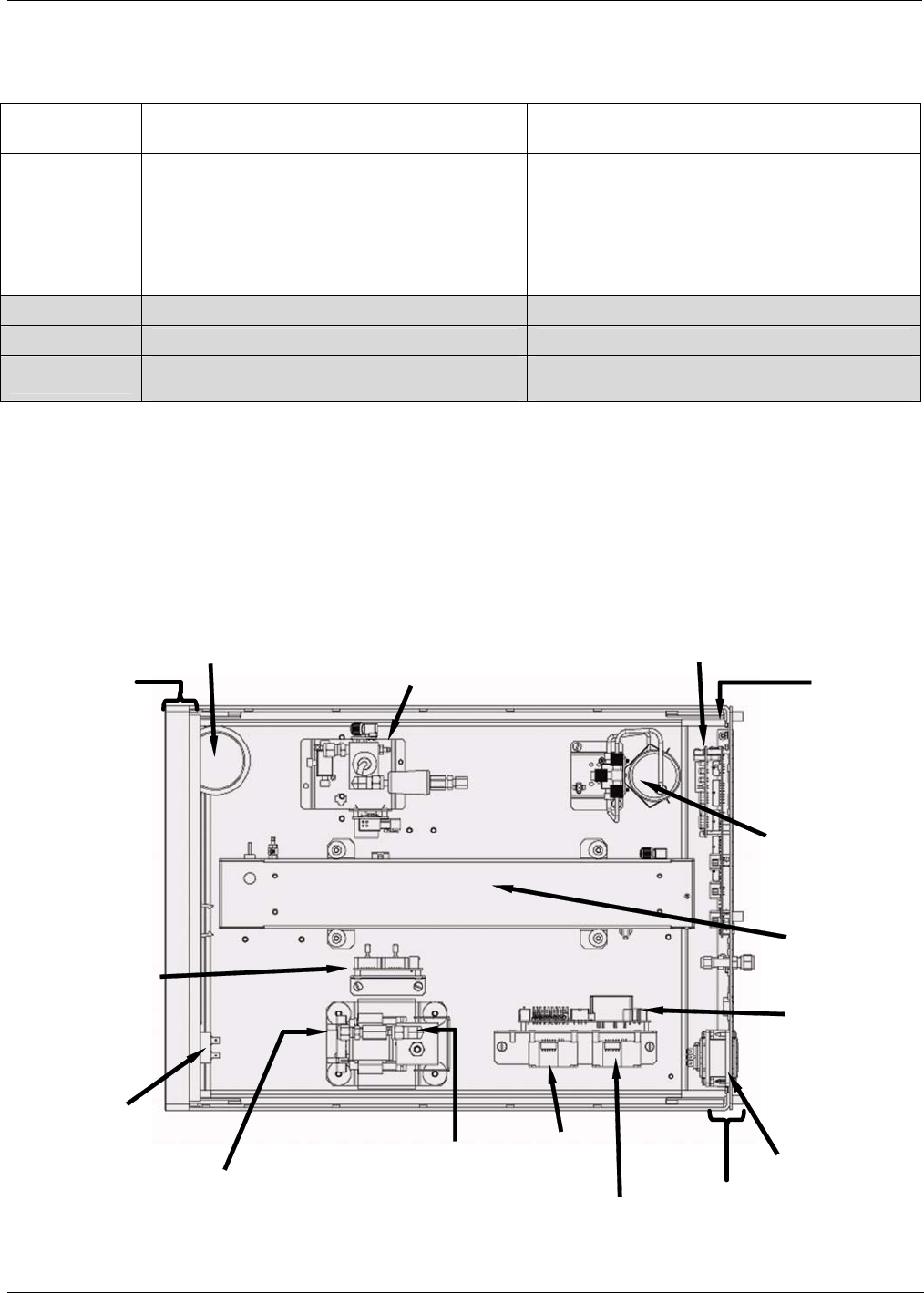
Particulate Filter
Gas Flow
Sensor Assy
ON/OFF
SWITCH
PS1
(+5 VDC; 15VDC)
PS2
(+12 VDC)
Pump Assy
Relay Board
IZS O
3
Generator
(Optional)
Optical
Bench
Critical Flow
Orifice
Front Panel
Rear Panel
PC
/
104 Card
Mother
Board
Power
Receptacle
Measure /
Reference
Valve
Figure 3-4: M400E Internal Layout – Top View with IZS Option
04315 Rev. C1 13