M400E Ozone Analyzer Operator’s Manual Table of Contents
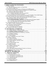
11.2.2.1. Critical Flow Orifice.................................................................................................................... 195
11.2.3. Particulate Filter................................................................................................................................ 196
11.2.4. Pneumatic Sensors........................................................................................................................... 196
11.2.4.1. Sample Pressure Sensor .......................................................................................................... 196
11.2.4.2. Sample Flow Sensor ................................................................................................................. 196
11.3. Electronic Operation ............................................................................................................................... 197
11.3.1. Overview........................................................................................................................................... 197
11.3.2. CPU .................................................................................................................................................. 198
11.3.3. Motherboard...................................................................................................................................... 198
11.3.3.1. A to D Conversion ..................................................................................................................... 198
11.3.3.2. Sensor Inputs ............................................................................................................................ 199
11.3.3.3. Thermistor Interface .................................................................................................................. 199
11.3.3.4. Analog Outputs.......................................................................................................................... 200
11.3.3.5. External Digital I/O..................................................................................................................... 200
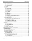
11.3.3.6. I
2
C Data Bus.............................................................................................................................. 200
11.3.3.7. Power Up Circuit........................................................................................................................ 200
11.3.4. Relay PCA ........................................................................................................................................ 200
11.3.4.1. Status LED’s.............................................................................................................................. 203
11.3.4.2. Watchdog Circuitry .................................................................................................................... 203
11.3.4.3. Valve Control............................................................................................................................. 204
11.3.4.4. Heater Control ........................................................................................................................... 204
11.3.4.5. Thermocouple Inputs and Configuration Jumper (JP5) ............................................................ 205
11.3.5. Power Supply/Circuit Breaker........................................................................................................... 206
11.3.5.1. Power Switch/Circuit Breaker.................................................................................................... 206
11.3.6. AC Power Configuration ................................................................................................................... 207
11.3.6.1. AC configuration – Internal Pump (JP7).................................................................................... 208
11.3.6.2. AC Configuration – Heaters for Option Packages (JP6)........................................................... 209
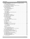
11.3.7. Photometer Layout and Operation.................................................................................................... 210
11.3.7.1. Photometer Electronic Operation .............................................................................................. 211
11.3.7.2. O
3
Photometer UV Lamp Power Supply ................................................................................... 212
11.3.7.3. Photometer Temperature .......................................................................................................... 213
11.3.7.4. Photometer Gas Pressure and Flow Rate................................................................................. 213
11.4. Interface.................................................................................................................................................. 214
11.4.1. Front Panel ....................................................................................................................................... 214
11.4.1.1. Front Panel Display ................................................................................................................... 215
11.4.1.2. Keypad ...................................................................................................................................... 215
11.4.1.3. Front Panel States LED’s .......................................................................................................... 215
11.5. Software Operation................................................................................................................................. 216
11.5.1. Adaptive Filter................................................................................................................................... 216
11.5.2. Calibration - Slope and Offset........................................................................................................... 217
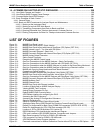
12. MAINTENANCE SCHEDULE & PROCEDURES .......................................................... 219
12.1. Predicting Failures Using the Test Functions......................................................................................... 219
12.2. Maintenance Schedule ........................................................................................................................... 220
12.3. Maintenance Procedures........................................................................................................................ 223
12.3.1. Replacing the Sample Particulate Filter............................................................................................ 223
12.3.2. Rebuilding the Sample Pump ........................................................................................................... 224
12.3.3. Replacing the IZS Option Zero Air Scrubber .................................................................................... 224
12.3.4. Performing Leak Checks .................................................................................................................. 225
12.3.4.1. Vacuum Leak Check and Pump Check..................................................................................... 225
12.3.4.2. Pressure Leak Check ................................................................................................................ 225
12.3.5. Performing a Sample Flow Check .................................................................................................... 226
12.3.6. Maintenance of the Photometer Absorption Tube............................................................................ 227
12.3.6.1. Cleaning or Replacing the Absorption Tube ............................................................................. 227
12.3.6.2. UV Lamp Adjustment................................................................................................................. 228
12.3.6.3. UV Lamp Replacement ............................................................................................................. 229
12.3.7. Adjustment or Replacement of Optional IZS Ozone Generator UV Lamp ....................................... 230
04315 Rev. C1 v


