


Advanced FEATURES of the M400E analyzer M400E Ozone Analyzer Operator’s Manual
7.3. SETUP MORE DIAG :THE DIAGNOSTIC MENU
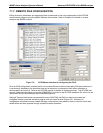
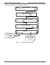
A series of diagnostic tools is grouped together under the SETUPMOREDIAG menu. As these parameters
are dependent on firmware revision, (see Appendix A). These tools can be used in a variety of troubleshooting
and diagnostic procedures and are referred to in many places of the maintenance and trouble-shooting sections
of this manual.
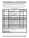
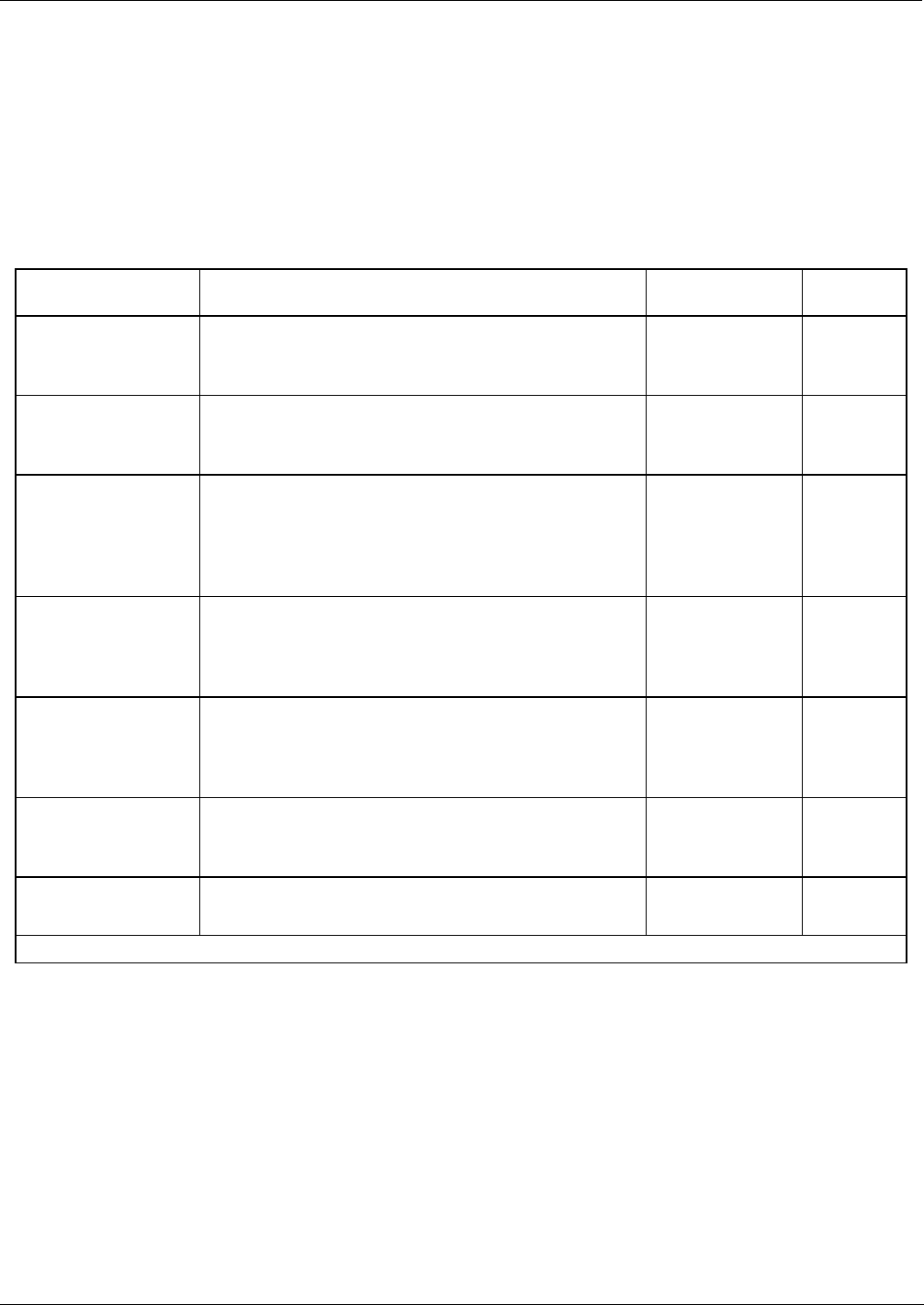
The various operating modes available under the
DIAG menu are:
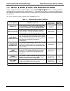
Table 7-5: Diagnostic Mode (DIAG) Functions
DIAG SUBMENU SUBMENU FUNCTION
Front Panel
Mode Indicator
MANUAL
SECTION
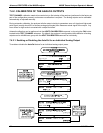
SIGNAL I/O
Allows observation of all digital and analog signals
in the instrument. Allows certain digital signals such
as valves and heaters to be toggled
ON and OFF.
DIAG I/O
13.1.3
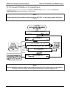
ANALOG OUTPUT
When entered, the analyzer performs an analog
output step test. This can be used to calibrate a
chart recorder or to test the analog output accuracy.
DIAG AOUT
13.7.7.1
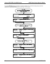
ANALOG I/O
CONFIGURATION
The signal levels of the instruments analog outputs
may be calibrated (either individually or as a group).
Various electronic parameters such as signal span,
and offset are available for viewing and
configuration.
DIAG AIO
7.4
O
3
GENERATOR
CALIBRATION
1
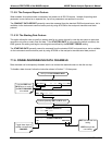
The analyzer is performing an electric test. This test
simulates IR detector signal in a known manner so
that the proper functioning of the sync/demod board
can be verified.
DIAG OPTIC
9.6
DARK
CALIBRATION
The analyzer is performing a dark calibration
procedure. This procedure measures and stores
the inherent dc offset of the sync/demod board
electronics.
DIAG ELEC
9.5.1
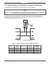
FLOW
CALIBRATION
This function is used to calibrate the gas flow output
signals of sample gas and ozone supply. These
settings are retained when exiting
DIAG.
DIAG FCAL
9.5.2
TEST CHAN
OUTPUT
Configures the
A4 analog output channel.
DIAG TCHN
7.4.6
1 Only appears if the IZS option is installed.
96 04315 Rev. C1