


Getting Started M400E Ozone Analyzer Operator’s Manual
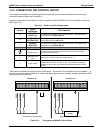
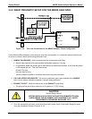
3.4.2. BASIC PNEUMATIC SETUP FOR THE M400E ANALYZER
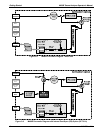
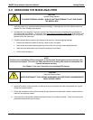
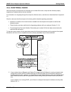
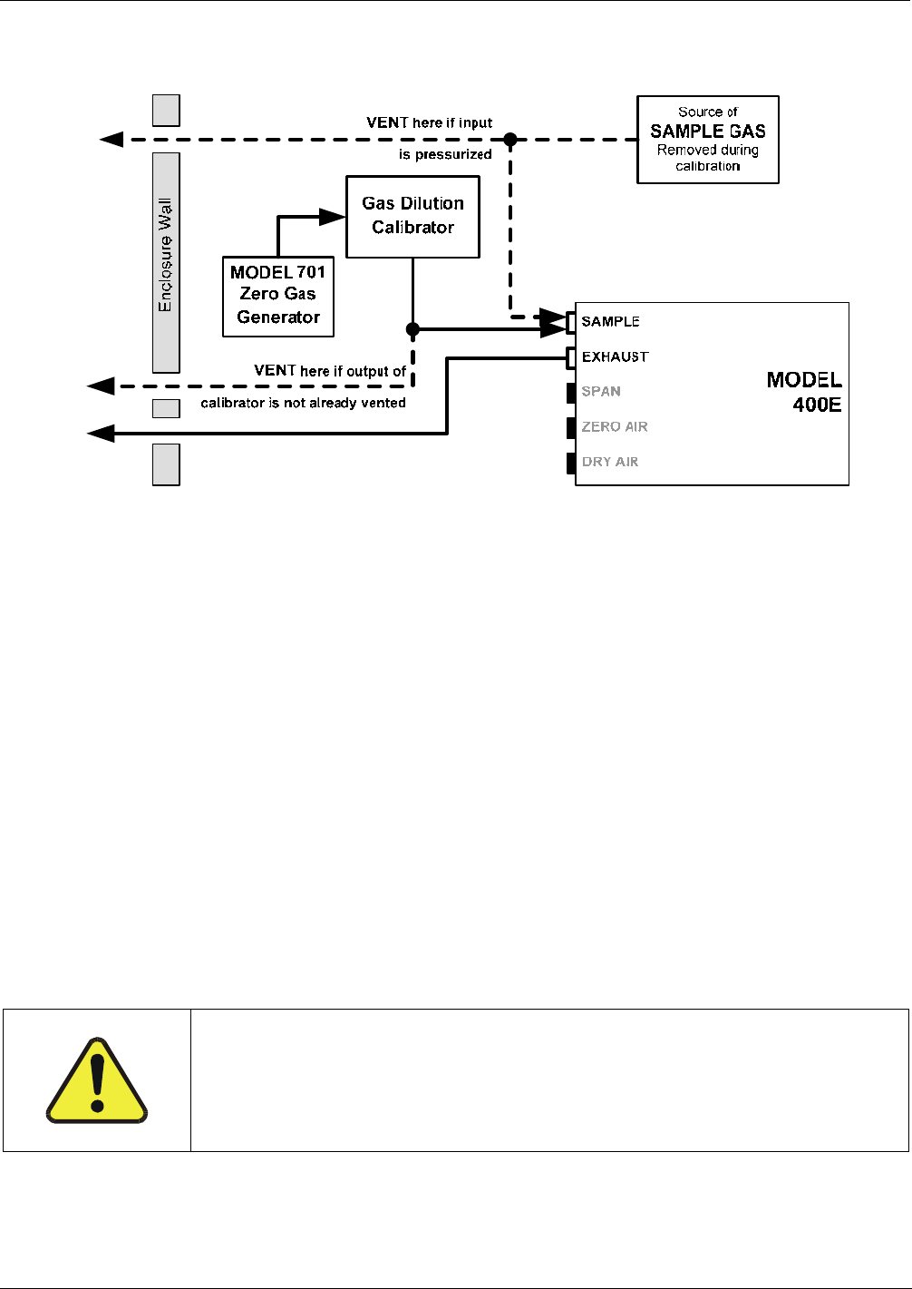
Figure 3-10: Gas Line Connections for the M400E Analyzer – Basic Configuration
For the Model 400E photometric ozone analyzer in its basic configuration (i.e. without the optional internal zero
air source or valves), attach the following pneumatic lines:
1. SAMPLE GAS SOURCE: Attach a sample inlet line to the sample inlet fitting.
Sample Gas pressure must equal ambient atmospheric pressure (1.0 psig)
In applications where the sample gas is received from a pressurized manifold, a vent must be placed
on the sample gas line. This vent line must be:
At least 0.2m long
No more than 2m long
Vented outside the shelter or immediate area surrounding the instrument
2. CAL GAS & ZERO AIR SOURCES: The source of calibration gas is also attached to the SAMPLE
inlet, but only when a calibration operation is actually being performed.
3. EXHAUST OUTLET: Attach an exhaust line to the EXHAUST outlet fitting.
The exhaust line should be a maximum of 10 meters of ¼” PTEF tubing.
CAUTION
General Safety Hazard
VENTING SHOULD BE OUTSIDE THE SHELTER OR IMMEDIATE AREA
SURROUNDING THE INSTRUMENT AND CONFORM TO ALL SAFETY
REQUIREMENTS REGARDING EXPOSURE TO O
3
.
4. Once the appropriate pneumatic connections have been made, check all pneumatic fittings for leaks
using the procedures defined in Section 12.3.4.
22 04315 Rev. C1