


M400E Ozone Analyzer Operator’s Manual Theory of Operation
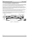
The A/D consists of a voltage-to-frequency (V-F) converter, a programmable logic device (PLD), three
multiplexers, several amplifiers and some other associated devices. The V-F converter produces a frequency
proportional to its input voltage. The PLD counts the output of the V-F during a specified time, and sends the
result of that count, in the form of a binary number, to the CPU.
The A/D can be configured for several different input modes and ranges but in the M400E is used in uni-polar
mode with a +5V full scale. The converter includes a 1% over and under-range. This allows signals from –
0.05V to +5.05V to be fully converted.
For calibration purposes, two reference voltages are supplied to the A/D converter: Reference ground and
+4.096 VDC. During calibration, the device measures these two voltages, outputs their digital equivalent to the
CPU. The CPU uses these values to compute the converter’s offset and slope and uses these factors for
subsequent conversions. See Section 7.4.7 for instructions on performing this calibration.
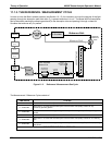
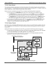
11.3.3.2. Sensor Inputs
The key analog sensor signals are coupled to the A/D through the master multiplexer from two connectors on
the motherboard. 100K terminating resistors on each of the inputs prevent cross talk from appearing on the
sensor signals.
O
3
DETECTOR OUTPUT: This is the primary signal used in the computation of the O
3
concentration.
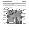
GAS PRESSURE SENSOR: This sensor measures the gas pressure in the sample chamber upstream
of the critical flow orifice (see Figure 3-5). The sample pressure is used by the CPU to calculate O
3
Concentration.
GAS FLOW SENSOR: This sensor measures the flow rate of the sample gas through the instrument.
This information is used as a diagnostic tool for determining gas flow problems
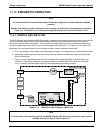
11.3.3.3. Thermistor Interface
This circuit provides excitation, termination and signal selection for several negative-coefficient, thermistor
temperature sensors located inside the analyzer. They are:
SAMPLE TEMPERATURE SENSOR: The source of this signal is a thermistor attached to the absorption
tube inside the optical bench assembly. It measures the temperature of the sample gas in the chamber.
This data is used to during the calculation of the O
3
concentration value.
UV LAMP TEMPERATURE SENSOR: This thermistor, attached to the UV lamp in the optical bench
reports the current temperature of the Lamp to the CPU as part of the lamp heater control loop.
IZS LAMP TEMPERATURE SENSOR: This thermistor attached to the UV lamp of the O
3
generator in the
IZS option reports the current temperature of that lamp to the CPU as part of control loop that keeps the
lamp constant temperature.
BOX TEMPERATURE SENSOR: A thermistor is attached to the motherboard. It measures the
analyzer’s inside temperature. This information is stored by the CPU and can be viewed by the user for
troubleshooting purposes via the front panel display. (See Section 13.1.2).
04315 Rev. C1 199