


Theory of Operation M400E Ozone Analyzer Operator’s Manual
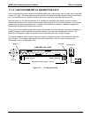
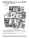
11.1.3. THE REFERENCE / MEASUREMENT CYCLE
In order to solve the Beer-Lambert equation (see Section 10.1.2) it is necessary to know the intensity of the light
passing through the absorption path both when O
3
is present and when it is not. The Model 400E accomplishes
this be alternately sending the sample gas directly to the absorption tube and passing it through a chemical
Scrubber that removes any O
3
present.
Flow / Pressure
Sensor PCA
SAMPLE
PRESSURE
SENSOR
O
3
FLOW
SENSOR
Sample Gas
Flow Control
EXHAUST
GAS
OUTLET
PUMP
DRY AIR
INLET
O
3
Scrubber
ABSORPTION TUBE
SAMPLE
GAS INLET
SPAN GAS
INLET
ZERO AIR
INLET
Measure/
Reference
Valve
Measure Path
Reference Path
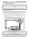
Figure 11-2: Reference / Measurement Gas Cycle
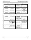
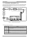
The Measurement / Reference Cycle consists of:
TIME INDEX STATUS
0 seconds Measure/Reference Valve Opens to the Measure Path.
0 – 2 seconds
Wait Period. Ensures that the Absorption tube has been adequately flushed of any
previously present gasses.
2 – 3 seconds
Analyzer measures the average UV light intensity of O
3
bearing Sample Gas (I) during this
period.
3 seconds Measure/Reference Valve Opens to the Reference Path.
3 – 5 seconds
Wait Period. Ensures that the Absorption tube has been adequately flushed of O
3
b3earing
gas.
5 – 6 seconds
Analyzer measures the average UV light intensity of Non-O
3
bearing Sample Gas (I
0
) during
this period.
CYCLE REPEAT EVERY 6 SECONDS
192 04315 Rev. C1