


Theory of Operation M400E Ozone Analyzer Operator’s Manual
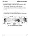
11.3.5. POWER SUPPLY/CIRCUIT BREAKER
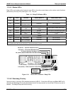
The analyzer operates on 100 VAC, 115 VAC or 230 VAC power at either 50 Hz or 60Hz. Individual instruments
are set up at the factory to accept any combination of these five attributes. Power enters the analyzer through a
standard IEC 320 power receptacle located on the rear panel of the instrument. From there it is routed through
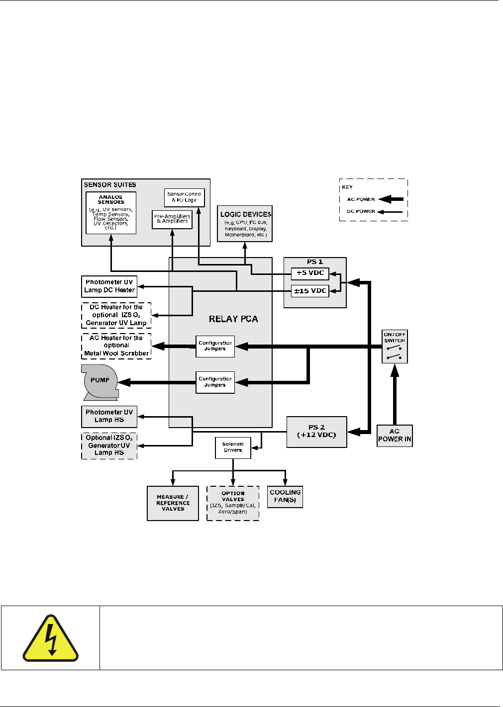
the ON/OFF Switch located in the lower right corner of the Front Panel.
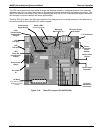
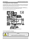
AC Line power is stepped down and converted to DC power by two DC Power Supplies. One supplies +12
VDC, for various valves and valve options, while a second supply provides +5 VDC and 15 VDC for logic and
analog circuitry as well as the power supplies for the Photometer and IZS UV Lamps.
All AC and DC Voltages are distributed via the relay PCA.
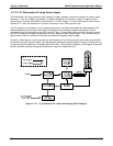
Figure 11-12: Power Distribution Block Diagram
11.3.5.1. Power Switch/Circuit Breaker
A 6.75 Amp circuit breaker is built into the ON/OFF Switch.
CAUTION
Should the AC power circuit breaker trip, investigate and correct the condition
causing this situation before turning the analyzer back on.
206 04315 Rev. C1