


Theory of Operation M400E Ozone Analyzer Operator’s Manual
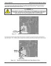
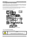
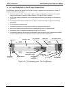
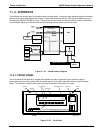
11.3.7. PHOTOMETER LAYOUT AND OPERATION
The Photometer is where the absorption of UV light by ozone is measured and converted into a voltage. It
consists of several sub-assemblies:
A mercury-vapor UV lamp. This lamp is coated in a material that optically screens the UV radiation
output to remove the O
3
producing 185nm radiation. Only light at 254nm is emitted.
An AC power supply to supply the current for starting and maintaining the plasma arc of the mercury
vapor lamp.
A thermistor and DC heater attached to the UV lamp to maintain the lamp at an optimum operating
temperature.
42 cm long quartz absorption tube.
A thermistor attached to the quartz tube for measuring sample gas temperature.
Gas inlet and outlet mounting blocks that rout sample gas into and out of the photometer.
The vacuum diode, UV detector that converts UV light to a DC current.
A preamplifier assembly, which convert the Detector’s current output into a DC Voltage then amplifies it
to a level readable by the A to D converter circuitry of the instrument’s motherboard
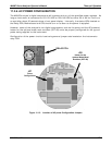
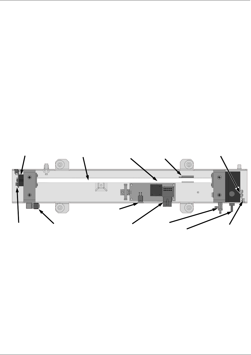
Absorption Tube
UV Lamp Heater
Control PCA
Sample Gas
Outlet
UV Lamp Power
Transformer
Power Connector
from
+15 VDC power supply
UV Lamp Power
Supply
(200 VAC @ 30 kHz)
Sam
p
le Gas Inlet UV Detector
Preamp PCA
UV Detector
Sample Gas
Thermistor
UV Lamp
UV Lamp Thermistor
(UV Lamp Heater Behind Thermistor)
Figure 11-16: O
3
Photometer Layout – Top Cover Removed
210 04315 Rev. C1